Crimping terminal structure for electrical appliance connector

A technology for crimping terminals and connectors, which is applied to the parts, connections, and connections where permanent deformation works in connection devices, etc., can solve the problems of high cost, slurry leakage, and increased connector production processes, and reduce production costs. , to ensure reliability and improve production efficiency

Active Publication Date: 2013-05-01
HENAN THB ELECTRIC
View PDF2 Cites 0 Cited by
  • Summary
  • Abstract
  • Description
  • Claims
  • Application Information

AI Technical Summary

Problems solved by technology

[0003] The object of the present invention is to provide a crimping terminal structure for electrical connectors, said crimping terminal structure for electrical connectors to solve the problems of crimping terminals in the prior art due to the through holes of the crimping terminals during injection molding. There will be slurry leakage, which will lead to the increase of the production process of the existing connector products, the high cost, and the technical problems of unreliable product quality

Method used


Image

  • Crimping terminal structure for electrical appliance connector
  • Crimping terminal structure for electrical appliance connector
  • Crimping terminal structure for electrical appliance connector

Examples


Embodiment 1

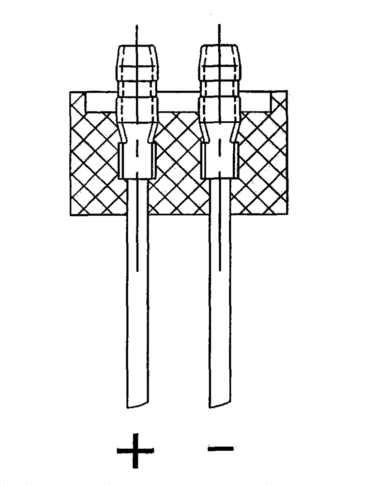
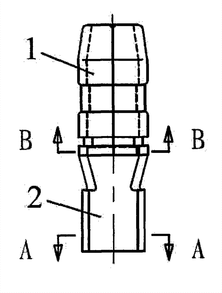
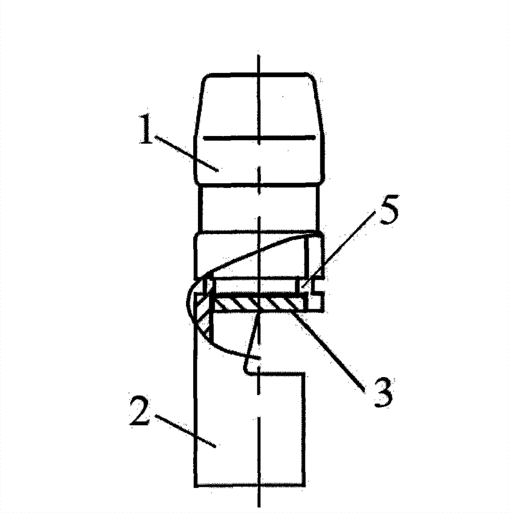
[0017] Such as figure 1 , figure 2 , image 3 , Figure 4 , Figure 5 and Figure 6 As shown, it is composed of a plug 1 and a wire crimping end 2. The plug part 1 is in the shape of a cylinder with a closed side wall, and the wire crimping end 2 is a curved surface structure that retains part of the side wall. The crimping terminal is packaged by an injection molding machine, wherein, A circular plate cover 3 is arranged at the lower end of the plug part. The circular plate cover 3 is formed by punching, and is connected with the side wall of the lower end of the plug through a small connecting section 4. A step 5 is provided in the inner hole of the lower end of the plug, and the step is the smallest. The diameter of the inner hole is smaller than the diameter of the disc cover, and the disc cover 3 and the stepped hole are tightly fitted.

[0018] In practice, the cylindrical structure of the plug part may also be a square cylinder with a square hole. At this time, th...


PUM


Abstract

The invention discloses a crimping terminal structure for an electrical appliance connector. The structure consists of a plug and a crimping end, wherein the plug part is in a cylindrical form of which the side wall is closed; the crimping end has a curved surface structure of which the side wall is partially preserved; a crimping terminal is encapsulated by an injection molding machine; the lower end of the plug part is provided with a round board cover which is formed by blanking and connected with the side wall at the lower end of the plug by a small connecting section; steps are formed inan inner hole at the lower end of the plug; the minimal inner hole diameter of the steps is less than the diameter of the round board cover; and the round board cover and the stepped holes are in close fit. In the crimping terminal structure for the electrical appliance connector, the lower end of the through hole of the plug part is provided with the round board cover, and the through hole of the plug part is blocked by the round board cover during the injection molding of the connector, so that slurry is not leaked during the injection molding, and a blocking piece does not need to be welded manually. Therefore, the production efficiency of connector products is improved, the production cost is lowered and the reliability of the products is ensured.

Description

Technical field: [0001] The invention relates to the field of electric appliances, in particular to connectors for automobile electric appliances and household electric appliances, in particular to a crimping terminal structure for electric appliance connectors. Background technique: [0002] Connector products widely used in automobile electrical appliances and household electrical appliances are composed of plastic shells, crimping terminals and wires. First, the crimping terminals and wires are crimped together, and then they are packaged together using injection molding equipment and injection molds. , to complete the entire product production process, in which the crimping terminal material is various metals, and the product is produced by a cold stamping die. In order to facilitate crimping with wires, the wire connection part at the rear end of the crimping terminal is set as a U-shaped open curved surface in cross section, while its front end is a cylindrical structu...

Claims


Application Information

Patent Timeline
Patent Type & Authority Patents(China)
IPC IPC(8): H01R13/02H01R4/18H01R13/405
Inventor 陈爱军王荣喜张玉亭
Owner HENAN THB ELECTRIC
Why Eureka
Try Eureka