
Limiting device and extruder

A technology of limiting device and extruder, which is applied in the direction of presses, material forming presses, manufacturing tools, etc., can solve the problems of difficulty in replacing extrusion cylinder components, "gluing, delaying replacement time, etc."

Active Publication Date: 2017-11-10
TAIZHONG TIANJIN BINHAI HEAVY MACHINERY
View PDF11 Cites 0 Cited by
  • Summary
  • Abstract
  • Description
  • Claims
  • Application Information

AI Technical Summary

Problems solved by technology

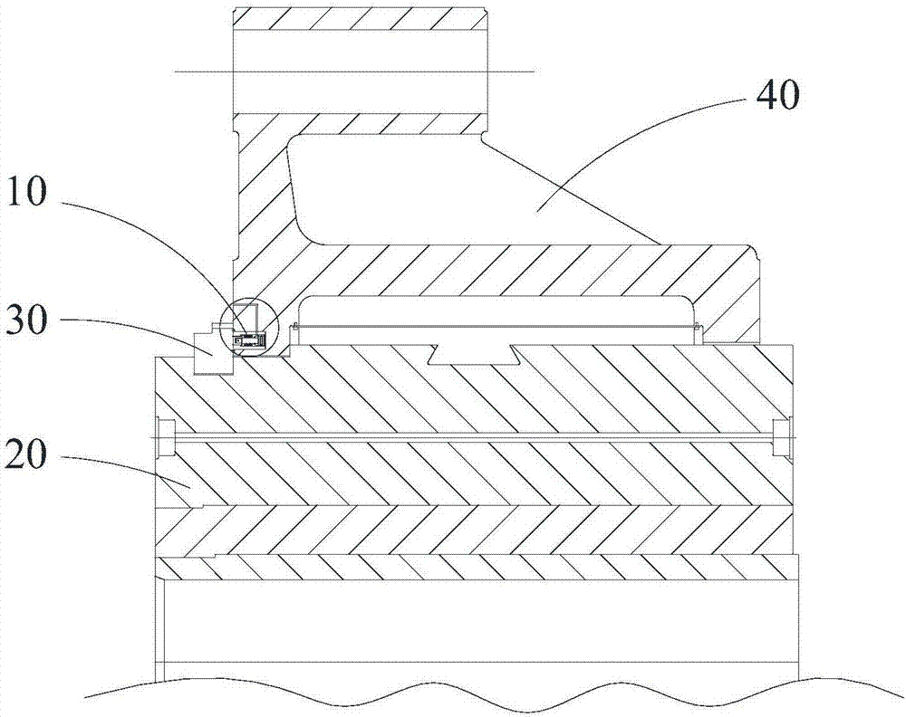
[0003] At present, the locking device of the extrusion barrel of the extrusion machine mostly adopts a manual deceleration motor through the reduction gear device to drive the inner hole to rotate 45° in the shape of a "plum blossom" large ring, to loosen the clamping control of the extrusion cylinder outer casing, and then carry out Replacement of the extrusion cylinder; during the entire replacement process, due to the inertia of the motor, it is often difficult to rotate the protrusion in the inner hole of the large ring gear to the position aligned with the slot designed on the outer casing of the extrusion cylinder, resulting in a smooth replacement Extrusion barrel; in addition, under the action of high temperature and high pressure, the large ring gear is prone to deformation during the contact process with the shell, and even "glue" occurs, making it difficult for the geared motor to drive the large ring gear to rotate, and it is difficult to replace the extrusion barrel components. Delayed replacement time and reduced work efficiency

Method used


Image

  • Limiting device and extruder
  • Limiting device and extruder
  • Limiting device and extruder

Examples


Embodiment Construction

[0026] Example embodiments will now be described more fully with reference to the accompanying drawings. Example embodiments may, however, be embodied in many forms and should not be construed as limited to the examples set forth herein; rather, these embodiments are provided so that this disclosure will be thorough and complete and will fully convey the concept of example embodiments to those skilled in the art. The described features, structures, or characteristics may be combined in any suitable manner in one or more embodiments. In the following description, numerous specific details are provided in order to give a thorough understanding of embodiments of the present disclosure. However, those skilled in the art will appreciate that the technical solutions of the present disclosure may be practiced without one or more of the specific details being omitted, or other methods, components, devices, steps, etc. may be adopted. In other instances, well-known technical solution...


PUM


Abstract

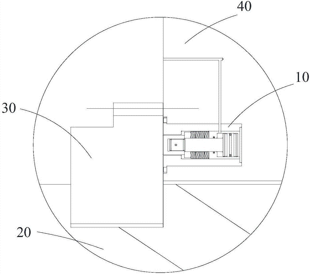
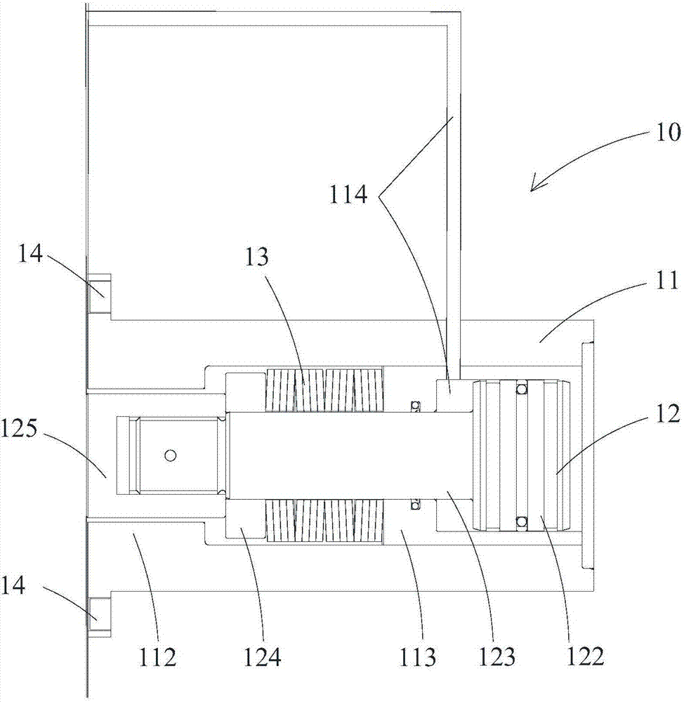
The invention relates to the technical field of extruder equipment, in particular to a limiting device and an extruder. The limiting device is used for limiting a gear ring with which an outer ring of an extrusion cylinder in the extruder is sleeved. The extruder further comprises an extrusion cylinder outer shell, the outer ring of the extrusion cylinder is sleeved with the extrusion cylinder outer shell, and the extrusion cylinder outer shell makes contact with the gear ring along the annular surface. The limiting device comprises a cylinder body, a piston and an elastic body, wherein the cylinder body is longitudinally arranged in the extrusion cylinder outer shell, one end of the cylinder body is open and faces the gear ring, the piston located in the cylinder body butts outwards through the elastic body arranged on the piston in a sleeving manner to enable a piston rod to stretch out of an opening of the cylinder body, and the big gear ring is further butted for limiting; besides, a drive access is further arranged in the cylinder body to make the piston retract to the opening of the cylinder body so that limiting butting of the piston rod to the big gear ring can be removed. By using the limiting device, the states that the end face of the big gear ring is not limited and the position is out of control are avoided, friction and abrasion generated during rotation are reduced, the efficiency for replacing an extrusion cylinder assembly is further improved, and the maintenance cost is further reduced.

Description

technical field [0001] The present disclosure relates to the technical field of extruder equipment, in particular, to a limiting device and an extruder. Background technique [0002] The extrusion barrel is an important part of the extrusion machine, which works under high temperature and high pressure conditions. During the operation of the extruder, the unit pressure of the extrusion cylinder can reach 400-500MPa, and the temperature can reach 350-500°C. The damage or failure of the extrusion cylinder components caused by this may occur from time to time. inevitable. [0003] At present, the locking device of the extrusion barrel of the extrusion machine mostly adopts a manual deceleration motor through the reduction gear device to drive the inner hole to rotate 45° in the shape of a "plum blossom" large ring, to loosen the clamping control of the extrusion cylinder outer casing, and then carry out Replacement of the extrusion cylinder; during the entire replacement proc...

Claims


Application Information

Patent Timeline
IPC IPC(8): B30B11/22B30B15/00
CPCB30B11/22B30B15/00
Inventor 王鑫吴凯凯
Owner TAIZHONG TIANJIN BINHAI HEAVY MACHINERY
Learn More