Eureka AIR delivers breakthrough ideas for toughest innovation challenges, trusted by R&D personnel around the world.

Intelligent LED lamp remote monitoring system

A technology of LED lamps and remote monitoring, applied in the direction of lamp testing, transmission system, signal transmission system, etc., can solve the problems of manufacturers failing to track product improvement and upgrading after sale, affecting the normal life and work of users, and inaccurate and timely content. Achieve the effect of improving its own value, low power consumption, and low operating current

Inactive Publication Date: 2011-02-16
邓志强
View PDF7 Cites 7 Cited by
  • Summary
  • Abstract
  • Description
  • Claims
  • Application Information

AI Technical Summary

Problems solved by technology

At present, there are many kinds of LED lamps on the market, and the selling price is much more expensive than other types of lighting products. In addition, consumers have relatively high quality requirements. In normal life and work, how to ensure the quality of their products and improve after-sales service has become the goal pursued by various manufacturers.
While doing a good job in production quality, how to track the condition of after-sales products when they are in use? At present, such products sold in the market are passively relying on consumers to provide feedback and provide information, and the content is not accurate and timely, which leads to the inability of manufacturers to do a good after-sales tracking and timely and effective improvement and upgrading of products.
Now the country advocates energy saving and emission reduction, and it has been well implemented. Many large public places, such as airports, stations, highways, etc., have replaced this energy-saving product, but once the product is damaged for some reason, it must be replaced. If it is not processed in time, it will bring great inconvenience to the user's work, life and travel

Method used


Image

  • Intelligent LED lamp remote monitoring system
  • Intelligent LED lamp remote monitoring system
  • Intelligent LED lamp remote monitoring system

Examples


Embodiment Construction

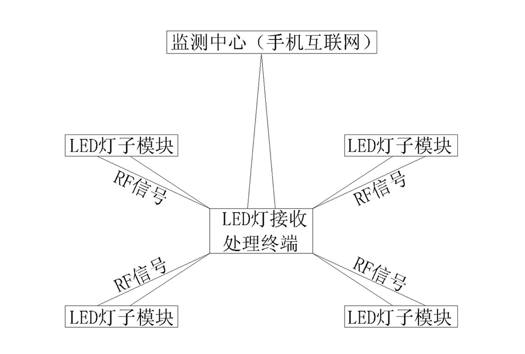
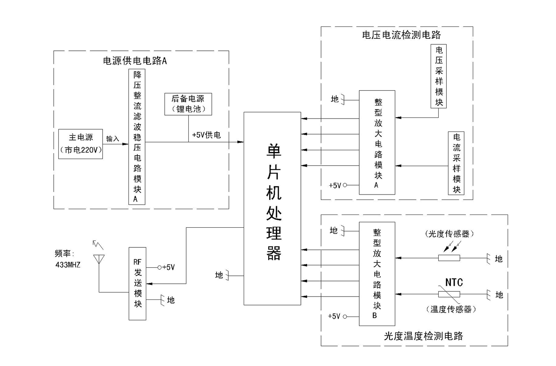
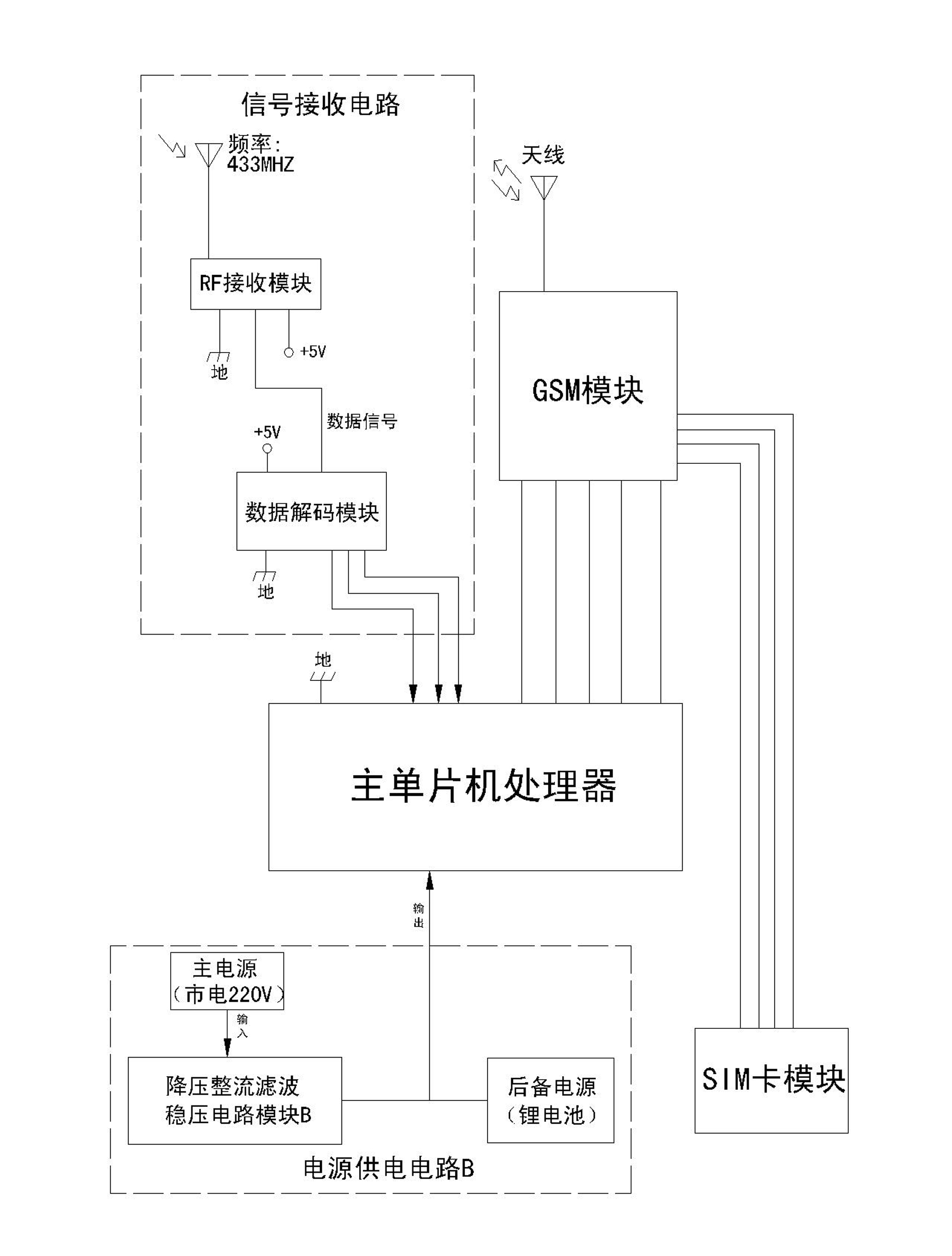
[0014] Such as Figure 1-Figure 3 As shown, the intelligent LED lamp remote monitoring system of the present invention includes an LED lamp sub-module installed in an LED lamp, an LED lamp receiving and processing terminal for analyzing and processing signals transmitted from the LED lamp sub-module, and a terminal for receiving LED lamps. The monitoring center of the information sent by the lamp receiving and processing terminal, and the LED lamp receiving and processing terminal realizes the information transmission with the monitoring center through the GSM module installed inside it, and the RF sending module is arranged in the LED lamp sub-module, and the The LED light sub-module transmits the signal to the LED light receiving and processing terminal through the RF sending module. And the receiving and processing terminal of the LED light can be expanded according to the actual usage, but the monitoring center only needs to share one. Such as figure 2 As shown, the abo...


PUM


Abstract

The invention relates to an intelligent LED lamp remote monitoring system which comprises an LED lamp sub module, an LED lamp receiving and processing terminal and a monitoring centre. The LED lamp receiving and processing terminal realizes information transfer with the monitoring centre through a GSM (Global System for Mobile Communications) module arranged inside the LED lamp receiving and processing terminal. The LED lamp sub module is internally provided with an RF (Radio Frequency) transmitting module and transmits signals to the LED lamp receiving and processing terminal. In the invention, the LED lamp sub module is internally provided with the RF transmitting module and effectively combined with LED lamp inductive sensing technology, short distance high-frequency communication technology and GSM remote network communication technology to form the remote monitoring system. The remote monitoring system can perform remote realtime monitoring for single group or multiple groups of LED lamps. The users or manufacturers can obtain the work condition of each group of LED lamps at the first time, thereby, the after-sales service level of products is improved and the product quality improving and upgrading period is shortened.

Description

technical field [0001] The invention relates to an electronic wireless monitoring product, in particular to an intelligent LED lamp remote monitoring system. Background technique [0002] With the promotion and popularization of LED energy-saving lamps, the role of after-sales and maintenance has become more important. At present, there are many kinds of LED lamps on the market, and the selling price is much more expensive than other types of lighting products. In addition, consumers have relatively high quality requirements. For normal life and work, how to ensure the quality of their products and improve after-sales service has become the goal pursued by various manufacturers. While doing a good job in production quality, how to track the condition of after-sales products when they are in use? At present, such products on the market are passively relying on consumers to provide feedback and information, and the content is not accurate and timely, which makes manufacturer...

Claims


Application Information

Patent Timeline
Patent Type & Authority Applications(China)
IPC IPC(8): H04L29/08G01R31/44H04W4/14G08C17/02
Inventor 邓志强
Owner 邓志强
Why Eureka
Eureka Blog
Learn More