Communication method and power line communication terminal
A technology of power line communication and communication mode, which is applied in the direction of multiplex communication, distribution line transmission system, signal transmission/reception through power distribution, etc., which can solve the problems of data communication error, drop, and unavoidable communication speed, etc. Achieve the effect of suppressing the decrease of communication speed
- Summary
- Abstract
- Description
- Claims
- Application Information
AI Technical Summary
Problems solved by technology
Method used
Image
Examples
no. 1 Embodiment approach
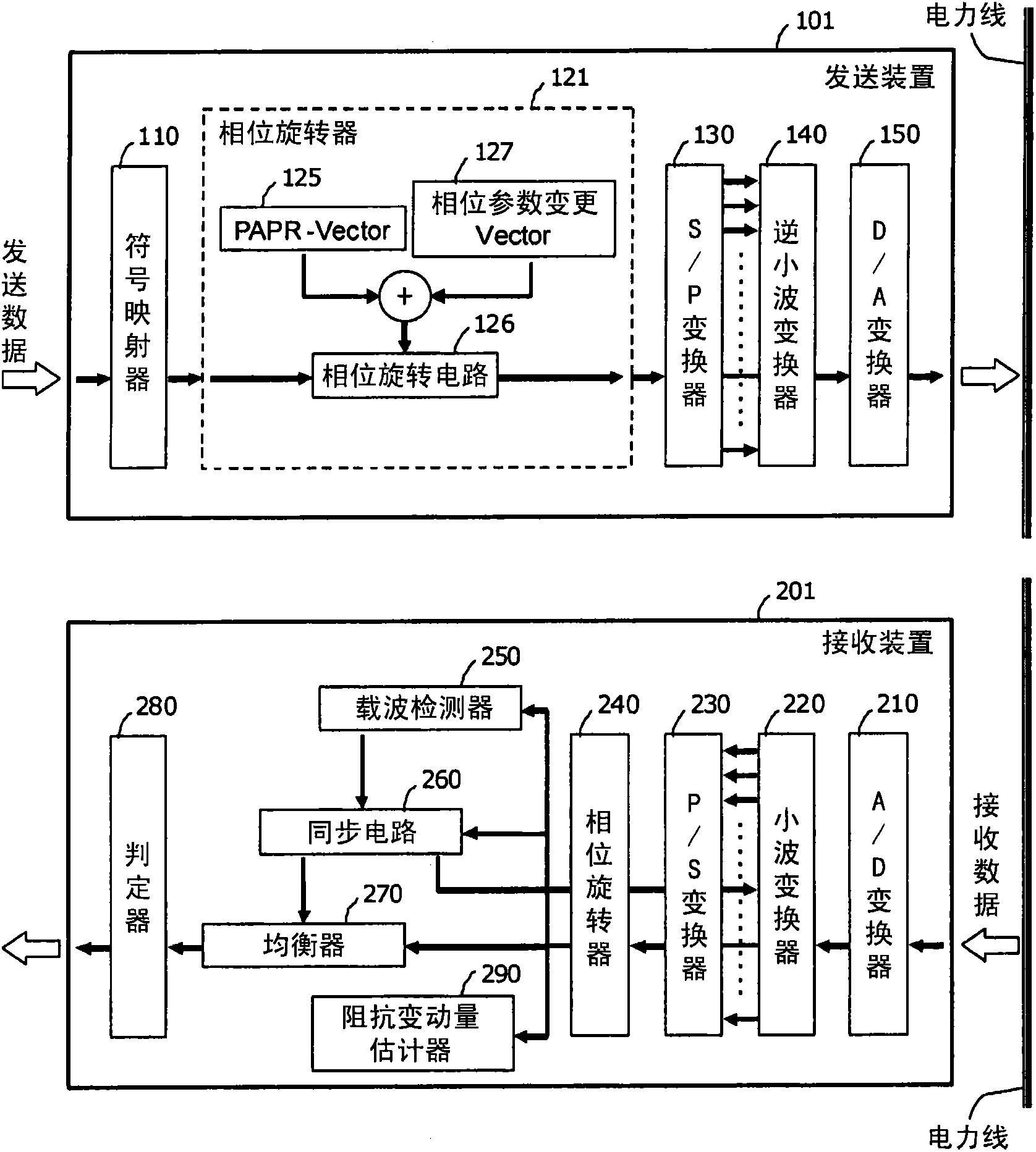
[0087] figure 1 It is a block diagram showing a schematic configuration of the power line communication system according to the first embodiment. The communication system uses power lines as a communication medium, and communicates between the sending device 101 and the receiving device 201 through multi-carrier transmission. Here, a case where wavelet-based OFDM is used as a multicarrier transmission method will be described as an example.
[0088] exist figure 1 Among them, the transmitting device 101 is composed of the following components: a symbol mapper 110, which performs symbol mapping on the bit string as transmission data; a phase rotator 121, which performs phase rotation on the symbol-mapped data; a serial-to-parallel converter (S / P converter) 130, carry out serial parallel transformation to the data after phase rotation; Inverse wavelet transformer 140, carry out inverse wavelet transformation on this real value on the time axis, produce the sampling value se...
no. 2 Embodiment approach
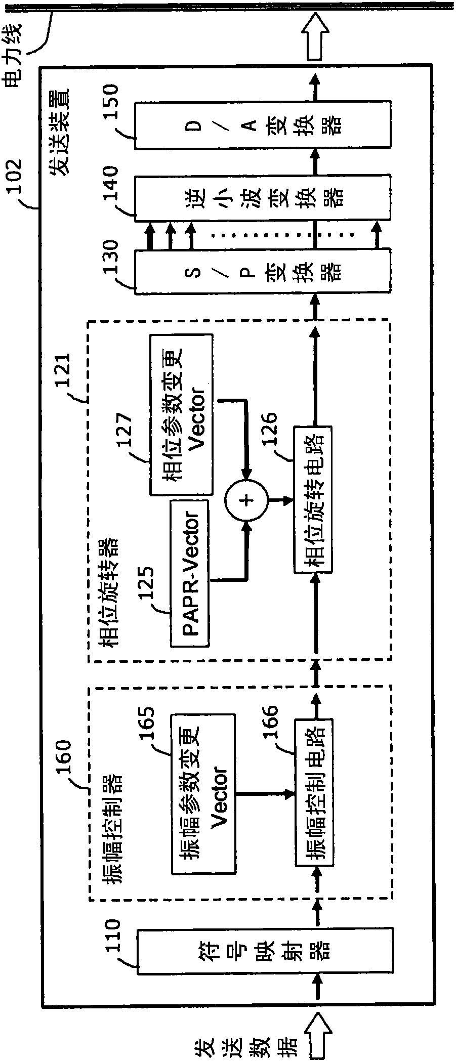
[0108] In the power line communication system according to the second embodiment, in image 3 The sending device 102 shown and figure 1 Between the receiving devices 201 shown, communication based on a multi-carrier transmission method is performed using power lines as a communication medium. In addition, in image 3 In, with the 1st embodiment's figure 1 The same symbols in the symbols refer to the same constituent elements. In addition, here, a case where wavelet-based OFDM is used as a multicarrier transmission method will be described as an example.
[0109] A unique configuration of the transmitting device 102 according to the present embodiment is the amplitude controller 160 . In the first embodiment figure 1 In the configuration of the transmission apparatus 101 shown, the amplitude control of the transmission signal can also be performed by the symbol mapper 110 , but in this case, the amplitude value of each subcarrier is usually only determined according to ...
no. 3 Embodiment approach
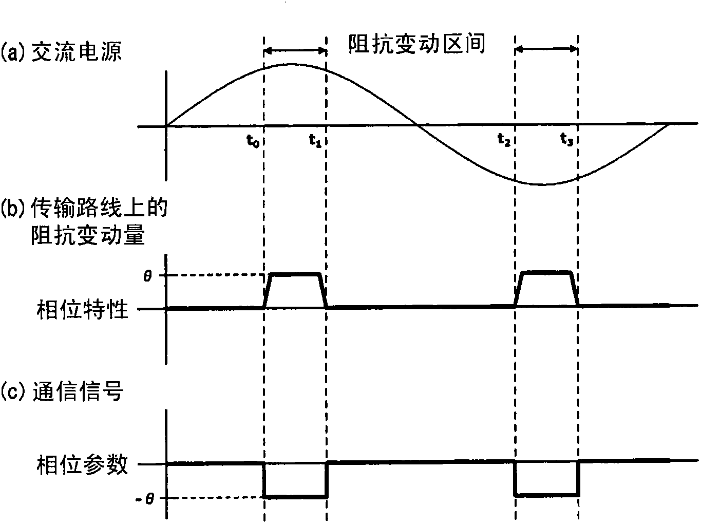
[0119] The difference between the third embodiment and the first and second embodiments is that in order to estimate the impedance of the transmission line between the transmission device 101 (or the transmission device 102, hereinafter only described as the transmission device 101) and the reception device 201 fluctuations without sending transmission line state estimation signals.
[0120] In the present embodiment, the impedance fluctuation amount of the transmission line is estimated by communication of normal data transmitted from the transmitting device 101 to the receiving device 201 . That is, if Figure 8 As shown, when normal data communication is performed, the receiving device 201 estimates the amount of impedance variation during reception of the symbol using the preamble 510 added to the head of the communication signal. The preamble symbol is, for example, a symbol in which all carriers are sine waves, and the receiving device 201 estimates the impedance variat...
PUM
 Abstract
Description
Claims
Application Information
 - Generate Ideas
- Intellectual Property
- Life Sciences
- Materials
- Tech Scout
- Unparalleled Data Quality
- Higher Quality Content
- 60% Fewer Hallucinations
Browse by: Latest US Patents, China's latest patents, Technical Efficacy Thesaurus, Application Domain, Technology Topic, Popular Technical Reports.
© 2025 PatSnap. All rights reserved.Legal|Privacy policy|Modern Slavery Act Transparency Statement|Sitemap|About US| Contact US: help@patsnap.com


