
Crossing signal light control method

A technology for signal light control and intersection, which is applied in the control of traffic signals and other directions, which can solve the problems of low utilization rate of green signal ratio and signal delay, and achieve the effect of reducing waiting time and improving utilization efficiency.

Active Publication Date: 2011-02-09
上海千年城市规划工程设计股份有限公司
View PDF5 Cites 38 Cited by
  • Summary
  • Abstract
  • Description
  • Claims
  • Application Information

AI Technical Summary

Problems solved by technology

[0007] The technical problem to be solved by the present invention is to overcome the problems of low utilization rate of green signal ratio and increase of signal delay in the prior art, and provide an intersection sensing signal based on traffic density, so as to adjust the signal according to the real-time change of traffic flow Phase timing, improving the utilization rate of the green signal ratio and reducing the delay signal light control method

Method used


Image

  • Crossing signal light control method
  • Crossing signal light control method

Examples


Embodiment Construction

[0031] A specific embodiment of the present invention is given below in conjunction with the accompanying drawings to describe the technical solutions and beneficial effects of the present invention in detail.

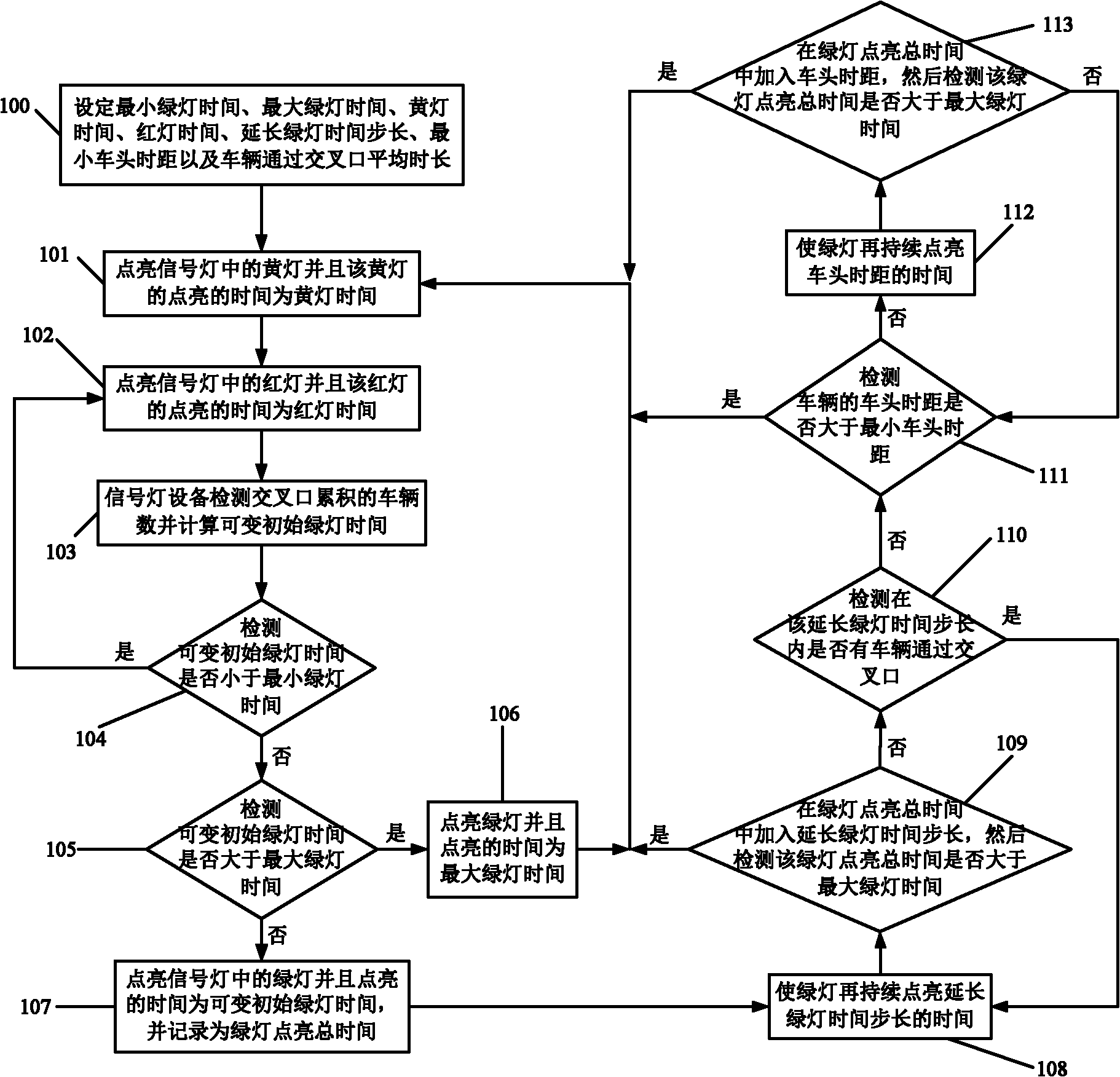
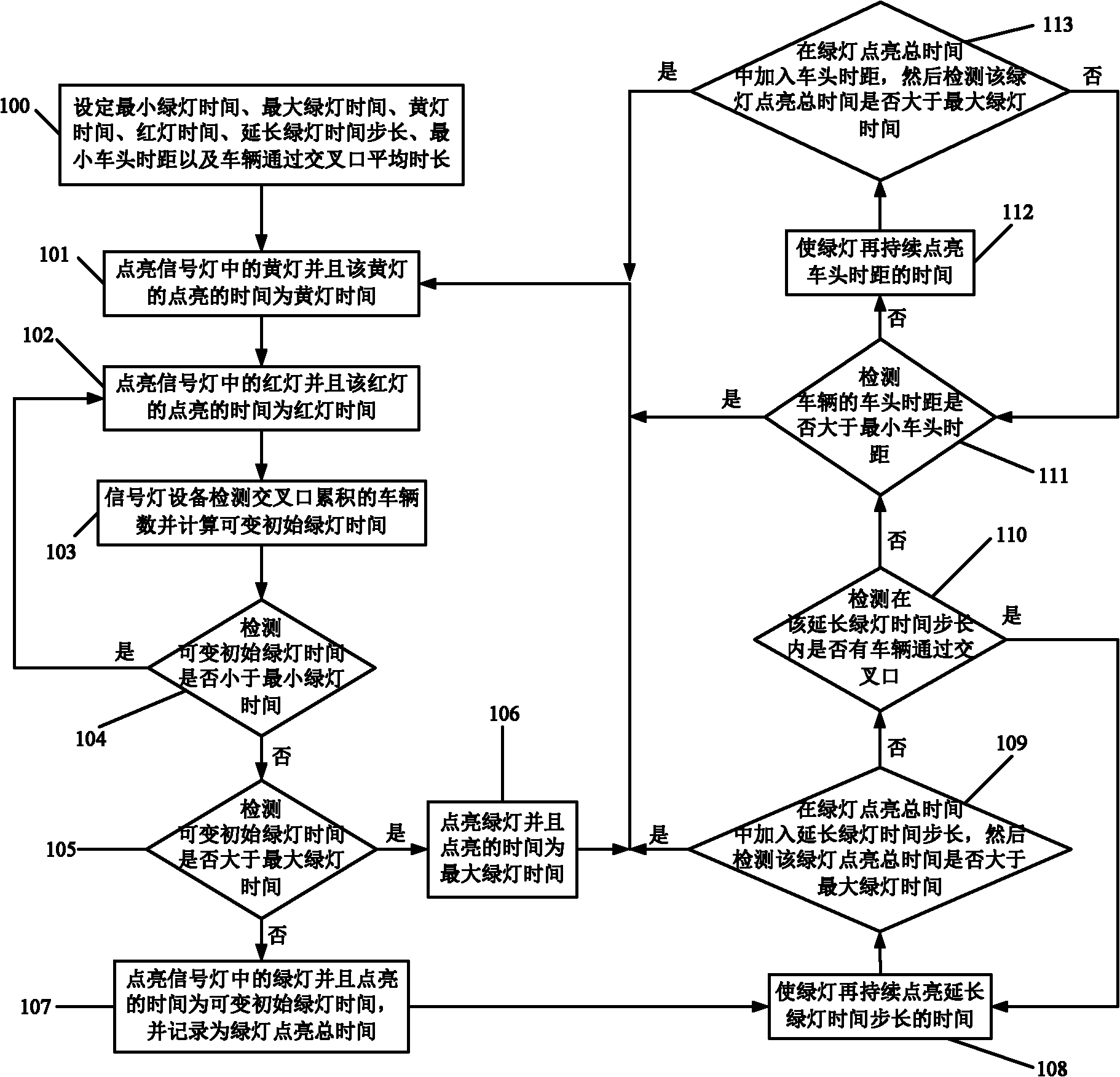
[0032] Such as figure 1 In a specific embodiment of the invention shown, the following steps are included.

[0033] Step 100 (i.e. the S in the claim 101 ), set the minimum green light time T in the signal light device in advance gmin , the maximum green light time T gmax , yellow light time T y , red light time T r , extend the green light time step T b , the minimum headway T gapmin and the average time for vehicles to pass through the intersection T average .

[0034] Step 101 (that is, the S in the claim 102 ), turn on the yellow light in the signal light, and the light time of the yellow light is the yellow light time T y .

[0035] Step 102 (that is, the S in the claim 103 ), light up the red light in the signal light, and the red light’s lighting ti...


PUM


Abstract

The invention discloses a crossing signal light control method comprising the following steps of: firstly determining the lighting time of a yellow light and a red light by setting yellow light time and red light time, lengthening green light time step length and prolonging minimum headway time; then acquiring variable initial green light time and prolonged green light time by detecting the headway time, whether vehicles pass through a crossing or not and the number of the vehicles accumulated at the crossing; and regulating the light time of a green light by controlling the variable initial green light time and the prolonged green light time. The crossing signal light control method changes the lighting time of the green light according to the flow demand and the traffic flow density of an access road of each crossing by controlling the variable initial green light time and the prolonged green light time and can dynamically regulate the prolonged green light time according to the arrival of the vehicles and the headway time, thereby instantaneously responding actual traffic demand, reducing the waiting time of the vehicles, effectively enhancing the use efficiency of the green light, improving the utilization ratio of split green ratio and decreasing the delay.

Description

technical field [0001] The invention relates to the technical field of traffic control, in particular to a signal lamp control method based on an intersection induction signal. Background technique [0002] Intersections that are closely related to traffic flow in urban core areas increasingly need to adopt regional network coordination control systems. However, in suburbs, high-tech parks, etc., where the traffic flow is not very large At intersections, the cost of networked control is too high, and timing control will cause a waste of efficiency in the use of signal lights. Many cities tend to adopt induction control. Inductive control overcomes the deficiency that timing control cannot respond to traffic demand in real time, and can adapt to random changes in traffic demand to a certain extent. [0003] Inductive control can be divided into two types from the perspective of implementation. [0004] (1) Semi-inductive control, usually suitable for the intersection of th...

Claims


Application Information

Patent Timeline
Patent Type & Authority Applications(China)
IPC IPC(8): G08G1/08
Inventor 徐笑晓
Owner 上海千年城市规划工程设计股份有限公司
Learn More