Regulating control mechanism for high-vacuum oil filling equipment and oil filling speed regulating method thereof

A technology for regulating control and oil-filling equipment, which is applied in the flow control of auxiliary non-electric power, etc., can solve the problems of low oil-filling efficiency and inability to adjust the oil-filling speed in a small amount, and achieve high oil-filling efficiency, small footprint, The effect of guaranteeing purity

Active Publication Date: 2012-05-30
KYKY TECH
View PDF0 Cites 0 Cited by
  • Summary
  • Abstract
  • Description
  • Claims
  • Application Information

AI Technical Summary

Problems solved by technology

[0006] For this reason, the technical problem to be solved by the present invention is that the high-vacuum oil-filling equipment in the prior art cannot micro-adjust the oil-filling speed, and the sealing caused by the frequent movement of the bell jar and the technology that requires frequent adjustment and installation or low oil-filling efficiency problem, and provide a method that can precisely adjust the oil filling speed in small quantities, and is not affected by the frequent movement of the bell jar to ensure the sealing of the vacuum chamber, and the frequent movement of the bell jar will not cause the need for frequent adjustments and installations, and can reduce equipment occupation. Adjustment control mechanism for high-vacuum oil-filling equipment with high space and oil-filling efficiency and its oil-filling speed regulation method

Method used


Image

  • Regulating control mechanism for high-vacuum oil filling equipment and oil filling speed regulating method thereof
  • Regulating control mechanism for high-vacuum oil filling equipment and oil filling speed regulating method thereof

Examples


Embodiment 1

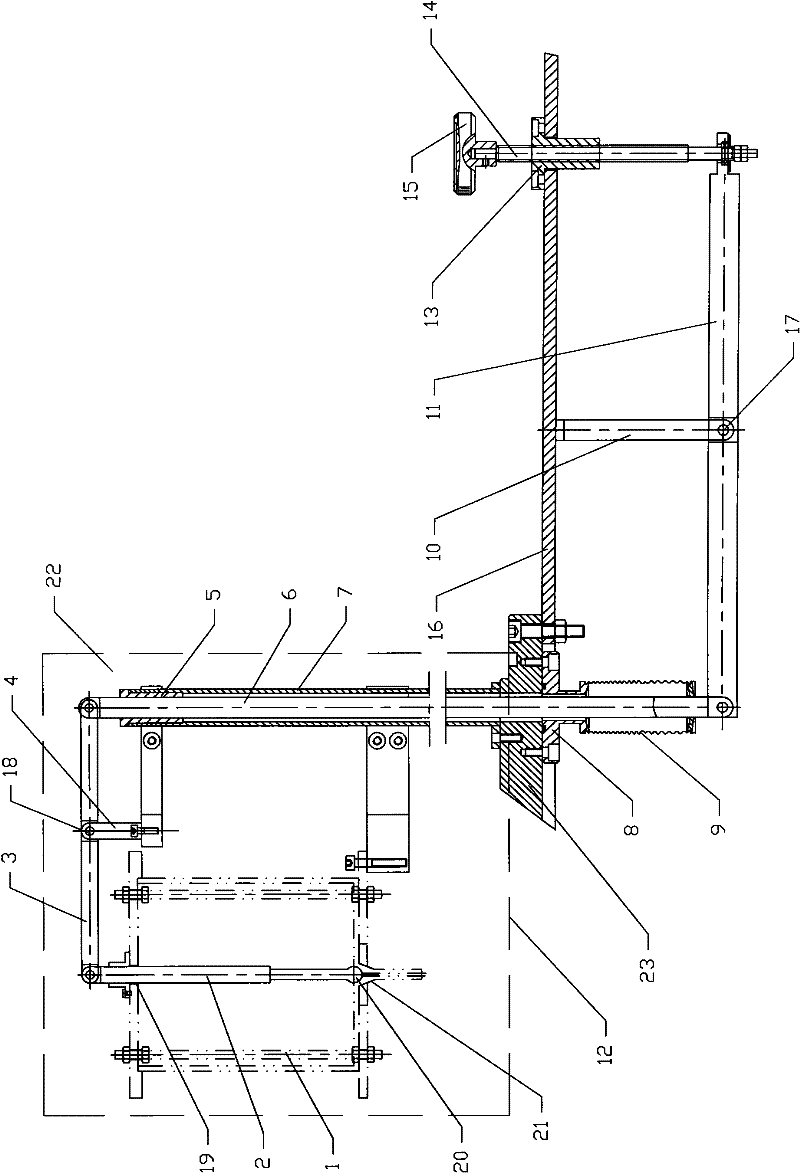
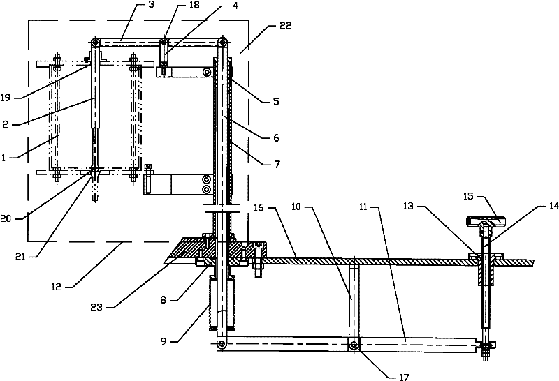
[0039] Such as figure 1 Shown is the preferred embodiment of the adjustment control mechanism for high vacuum oil-filled equipment of the present invention. The high vacuum oil-filled equipment includes common devices such as a vacuum chamber 22, an oil storage device, and a vacuum pumping device. Wherein, the vacuum chamber 22 includes a base plate 23 and a bell jar 12 placed on the base plate 23. In this embodiment, the bell jar 12 is a quartz bell jar. There is a sealing rubber ring, so that the vacuum chamber 22 can be sealed and evacuated; the oil storage device is an oil cup 1, and an oil outlet 21 is formed at the bottom of the oil cup 1. In this embodiment, the oil The outside of cup 1 is provided with a heating belt for oil refining.

[0040] The adjustment control mechanism includes a speed limiting lever 2, a guide control lever 6, an adjustment mechanism and a sliding sealing mechanism.

[0041] The speed limiting rod 2 is arranged in the vacuum chamber 22 , and...

Embodiment 2

[0049] The difference between the adjustment control mechanism of this embodiment and the first embodiment is that the adjustment mechanism in this embodiment is not a lever mechanism, but a figure 1 The guide control rod 6 and the adjustment rod 14 are directly fixedly connected through the connecting rod, as long as the guide control rod 6 can be linked with the adjustment rod 14, and the adjustment action of the adjustment rod 14 can be transferred to the guide control rod 6 is enough. When adjusting the oil filling speed, operate the control end of the adjustment rod 14 to adjust the relative distance between the speed limiting member 20 and the oil outlet 21 proportionally (including equal proportions, reduction or enlargement as required) through the lever mechanism in the chamber, Finally, the cross-sectional area of ​​the oil outlet 21 suitable for the passage of oil is changed to realize the adjustment of the oil filling speed. Other structures of the adjustment cont...

Embodiment 3

[0052] The difference between the adjustment and control mechanism of this embodiment and the first embodiment is that, for another example figure 1 As shown, in this embodiment, the guiding control rod 6 and the speed limiting rod 2 are directly fixedly connected by a connecting rod, as long as the guiding control rod 6 and the speed limiting rod 2 can be linked, the adjustment action can be transferred to the Speed ​​limit lever 2 is enough. When adjusting the oil filling speed, operate the control end of the adjusting lever 14 to adjust the relative distance between the speed limiting member 20 and the oil outlet 21 proportionally (including equal proportion, reduction or enlargement as required) through the external lever mechanism, Finally, the cross-sectional area of ​​the oil outlet 21 suitable for the passage of oil is changed to realize the adjustment of the oil filling speed. Other structures of the adjustment control mechanism in this embodiment are the same as tho...


PUM


Abstract

The invention provides a regulating control mechanism for high-vacuum oil filling equipment. The mechanism comprises a speed limiting rod, a guide control rod, a regulating mechanism and a sliding sealing mechanism, wherein the regulating mechanism controls the throttling end of the speed limiting rod by controlling the guide control rod so as to change the cross sectional area, which is suitablefor oil to pass through, of an oil outlet and control the oil filling speed of the oil outlet. The invention also provides an oil filling speed regulating method for filling oil into an inertia element by using the regulating control mechanism. In the method, the regulating mechanism is operated, the throttling end of the speed limiting rod is controlled by controlling the guide control rod, so that the cross sectional area, which is suitable for the oil to pass through, of the oil outlet of an oil storage device is changed and the oil filling speed of the oil outlet is controlled. The regulating control mechanism for the high-vacuum oil filling equipment and the oil filling speed regulating method thereof can accurately and slightly regulate the oil filling speed, ensure the air tightness of a vacuum chamber, reduce the occupied space of the equipment and improve oil filling efficiency.

Description

technical field [0001] The invention relates to the field of instruments and meters (analytical instruments), in particular to an adjustment control mechanism for high vacuum oil-filled equipment and an oil-filled speed regulating method for assisting in oil-filling inertial elements. Background technique [0002] In recent years, with the development of aviation, navigation industry and military technology, my country's demand for inertial sensing components and inertial navigation components, such as gyroscopes and accelerometers, has increased rapidly. These inertial components need to be exhausted and filled with oil (that is, oily substances such as insulating oil are injected into their inner cavities) to ensure their normal operation. [0003] The above oil filling process needs to be carried out in a high vacuum environment. This is because if the oil filling is performed in an atmospheric environment, the oil injected into the inertial element will contain a large n...

Claims


Application Information

Patent Timeline
Patent Type & Authority Patents(China)
IPC IPC(8): G05D7/03
Inventor 曹桂英
Owner KYKY TECH
Why Eureka
Try Eureka