Pneumatic lock

A pneumatic and air cylinder technology, applied in the field of special locks, can solve the problems of inability to meet safe transportation, damage by thieves, complicated installation, etc., and achieve the effects of not easy static electricity and sparks, simple structure, and good safety and explosion-proof performance.

Active Publication Date: 2012-12-26
大连量天科技发展股份有限公司
View PDF0 Cites 0 Cited by
  • Summary
  • Abstract
  • Description
  • Claims
  • Application Information

AI Technical Summary

Problems solved by technology

[0002] The environment of the oil tanker is harsh during transportation, and it is in a highly dangerous explosive gas environment. The explosion-proof requirements are high. The friction of the metal of the general mechanical lock is prone to static electricity, which is easy to cause accidents and cannot meet the needs of safe transportation.
Traditional door locks use micro motors to drive gears, chains and other intermediate components to drive the switch of the deadbolt. The structure is complex. The previous mechanical structure is fixed by means of exposed equipment, which is easily damaged by thieves. In addition, because the size of the deadbolt and the connecting rod is not fixed, Complicated installation

Method used


Image

  • Pneumatic lock

Examples


Embodiment Construction

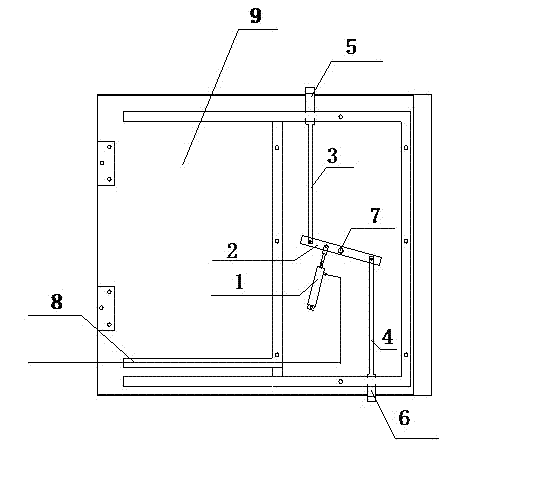
[0015] Such as figure 1 As shown, a pneumatic lock includes a cylinder 1, an active connecting rod 2, an upper driven connecting rod 3, a lower driven connecting rod 4, an upper bolt 5, a lower bolt 6, an air pipe 8, a door panel 9, and a door panel 9 There is a lock hole matched with the dead bolt, the upper driven connecting rod 3 is fixedly connected with the upper dead bolt 5, the lower driven connecting rod 4 is fixedly connected with the lower dead bolt 6, and there is a fixed fulcrum on the door panel 9, and the cylinder 1 One end of the cylinder 1 is connected with the fixed fulcrum, and the other end of the cylinder 1 is movably connected with the active connecting rod 2; The upper driven link 3 and the lower driven link 4 are movably connected respectively, and the active link 2 moves up and down with the support of the rotating shaft 7, driving the upper driven link 3 and the lower driven link 4 to move, thus completing the deadbolt lock. Snaps in and out of th...


PUM


Abstract

The invention discloses a pneumatic lock. The pneumatic lock comprises a cylinder (1), a drive connecting rod (2), an upper driven connecting rod (3), a lower driven connecting rod (4), an upper bolt (5), a lower bolt (6) and a door plate (9), and is characterized in that: the upper driven connecting rod (3) is fixedly connected with the upper bolt (5); the lower driven connecting rod (4) is fixedly connected with the lower bolt (6); the door plate (9) is provided with a fixed pivot; one end of the cylinder (1) is connected with the fixed pivot while the other end of the cylinder (1) is movably connected with the drive connecting rod (2); a shaft (7) is fixedly arranged on the door plate (9); the middle part of the drive connecting rod (2) is connected with the shaft (7) moveably; the two ends of the drive connecting rod (2) are respectively connected with the upper driven connecting rod (3) and the lower driven connecting rod (4) moveably; and the drive connecting rod (2) drives the upper driven connecting rod (3) and the lower driven connecting rod (4) to move under the action of the cylinder (1). The pneumatic lock has a simple structure and high safety.

Description

technical field [0001] The invention relates to a special lock used in the anti-theft field, in particular to a special anti-theft pneumatic lock for the fuel tank door of an oil tanker. Background technique [0002] The environment of tank trucks is harsh during transportation, in a highly dangerous explosive gas environment, and the explosion-proof requirements are high. The friction of the metal of the general mechanical lock is prone to static electricity, which is easy to cause accidents and cannot meet the needs of safe transportation. Traditional door locks use micro motors to drive gears, chains and other intermediate components to drive the switch of the deadbolt. The structure is complex. The previous mechanical structure is fixed by means of exposed equipment, which is easily damaged by thieves. In addition, because the size of the deadbolt and the connecting rod is not fixed, It is more cumbersome to install. Contents of the invention [0003] The object of th...

Claims


Application Information

Patent Timeline
Patent Type & Authority Patents(China)
IPC IPC(8): E05B51/02E05B63/14E05B65/52E05B15/16
Inventor 刘忠林郑欣曲葵生马成国吕林
Owner 大连量天科技发展股份有限公司
Why Eureka
Try Eureka