
Method and arrangement for detecting particles

A technology of particles and detectors, which is applied in the direction of measuring devices, instruments, and material analysis through electromagnetic means, and can solve problems such as contamination and non-detection

Inactive Publication Date: 2011-02-02
VOLVO TECH +1
View PDF1 Cites 11 Cited by
  • Summary
  • Abstract
  • Description
  • Claims
  • Application Information

AI Technical Summary

Problems solved by technology

At the other extreme is that conventional sensors neither detect sufficient amounts of particulate matter to provide meaningful readings, and in some applications they can become fouled due to overloading of particulate matter

Method used


Image

  • Method and arrangement for detecting particles
  • Method and arrangement for detecting particles
  • Method and arrangement for detecting particles

Examples


Embodiment Construction

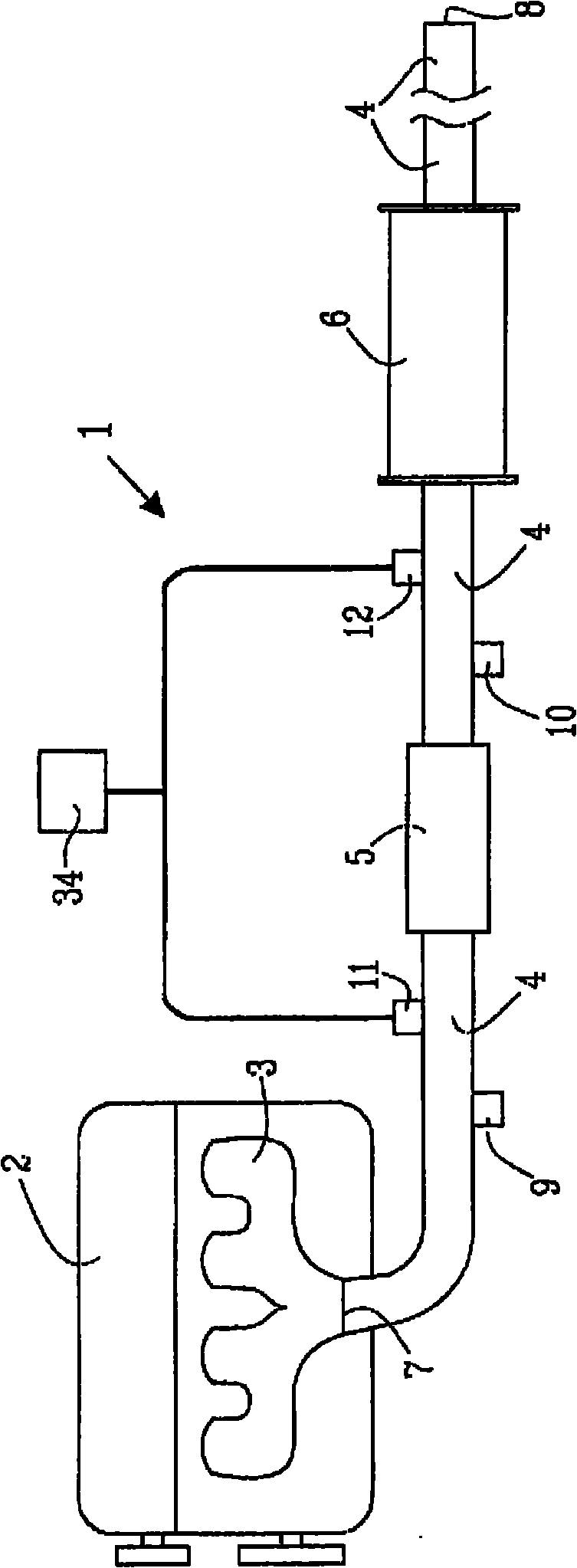
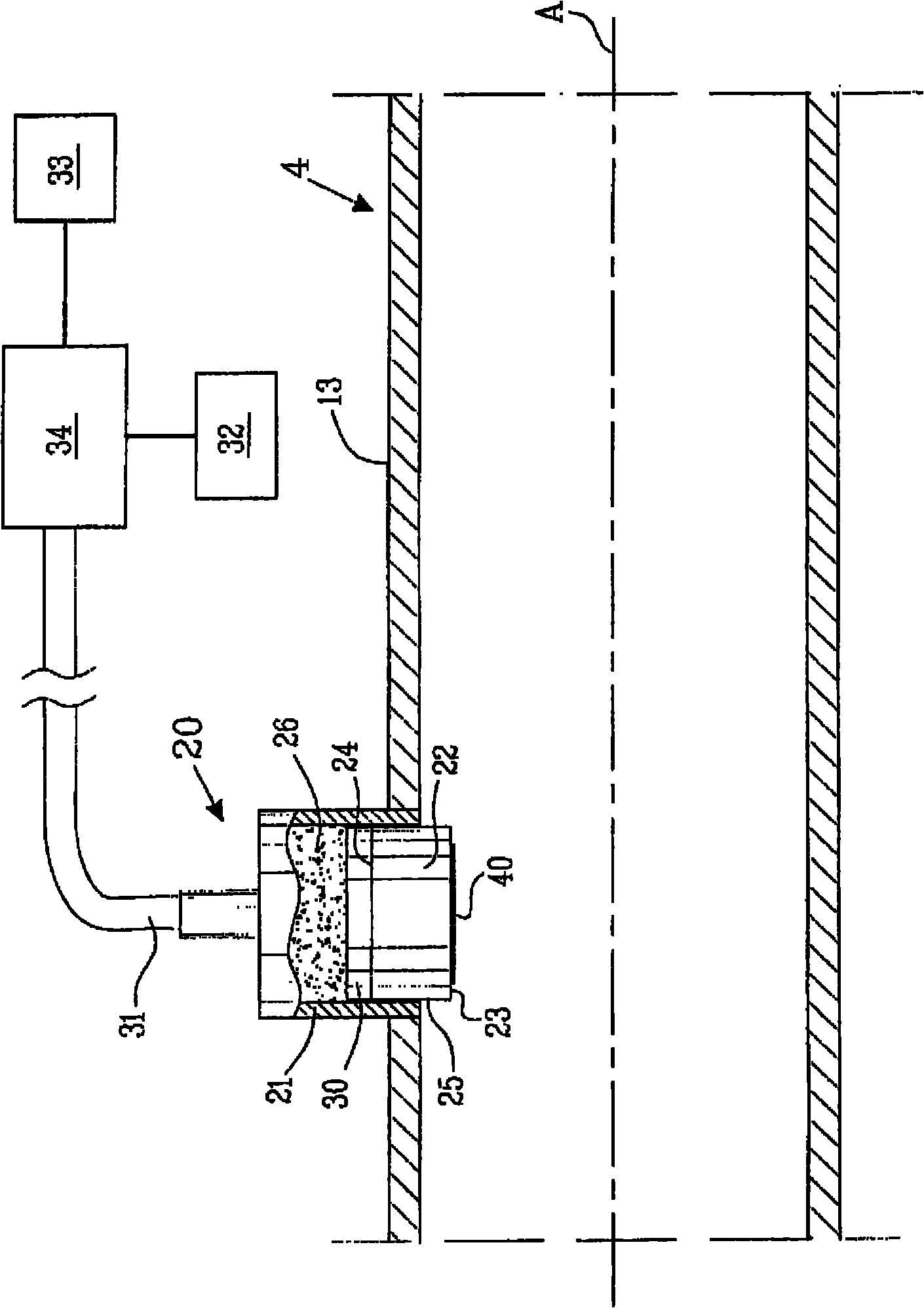
[0027] figure 1 A schematic illustration of an exhaust system 1 connected to a diesel engine 2 at an engine exhaust port 3 is shown. This exhaust system 1 is preferably used in a vehicle, such as a truck, boat, car, train, airplane or any other suitable vehicle. In the shown embodiment, the exhaust system 1 consists of an exhaust duct 4 , a diesel particle filter 5 and a muffler 6 . The exhaust duct 4 comprises an intake opening 7 through which exhaust gas from the engine 2 enters the exhaust system 1 , and an exhaust opening 8 through which exhaust gas exits the exhaust system 1 to ambient air. The first and second pressure sensors 9 , 10 are arranged on respective sides of the diesel particle filter 5 . Furthermore, the first and the second soot particle arrangement 11 , 12 according to the invention are arranged on respective sides of the diesel particle filter 5 . Although the invention is described herein with reference to soot particle sensor methods and arrangements,...


PUM


Abstract

The present invention relates to a method for detecting particles and a particle sensor arrangement. More specifically, the present invention relates to a method and arrangement for detecting particles in a gas flow, e.g. from a diesel combustion engine. The method comprises the steps of,forcing a particle build up on a sensor element of a particle sensor arrangement by regulating the sensor element to a second temperature,wherein the second temperature is lower than a first temperature, the first temperature being the gas flow temperature. Additionally is the particle build up detected at the sensor element by means of a detector. The present invention provides for an accurate method and arrangement to detect and thereby measure particles present in a gas flow, e.g. from a combustion engine.

Description

technical field [0001] The invention relates to a method for detecting particles and a particle sensor arrangement. More specifically, the present invention relates to a method and arrangement for detecting particles in a gas flow. Background technique [0002] There is an increasing demand for environmentally friendly vehicles, engines, fuels and vehicle exhaust cleaning arrangements, all in an effort towards less harmful impact on the environment. In the field of vehicle exhaust cleaning, the industry faces a microsecond balance: to provide the sufficient engine effect that consumers demand without emitting large amounts of harmful emissions (such as NOx, COx, hydrocarbons, particulates, and similar discharge). Not only consumers but also legislators are driving the need to have internal combustion engines and exhaust cleaning systems that aim for zero emissions. Consequently, an increased awareness in the vehicle industry of the need for environmentally friendly soluti...

Claims


Application Information

Patent Timeline
Patent Type & Authority Applications(China)
IPC IPC(8): G01N27/12
CPCG01N27/4077G01N15/0255
Inventor 雅科·菲瑟彼得·约饶多伊纳·卢蒂克安尼塔·劳埃德斯佩茨梅里·萨纳蒂
Owner VOLVO TECH
Learn More