
Instrument step motor with large rotor and low speed ratio

A technology of instruments and magnet rotors, applied in electrical components, electromechanical devices, etc., can solve the problems of large reduction ratio, difficult assembly, and difficult gear processing.

Inactive Publication Date: 2011-02-02
宁波九菱电机有限公司
View PDF1 Cites 1 Cited by
  • Summary
  • Abstract
  • Description
  • Claims
  • Application Information

AI Technical Summary

Problems solved by technology

[0003] The purpose of the present invention is to solve the problems in the prior art that require a large reduction ratio, which causes great difficulty in gear processing and assembly, and provide a movement with a large-diameter magnet rotor, low speed ratio, and easy manufacturing and assembly.

Method used


Image

  • Instrument step motor with large rotor and low speed ratio
  • Instrument step motor with large rotor and low speed ratio

Examples


Embodiment Construction

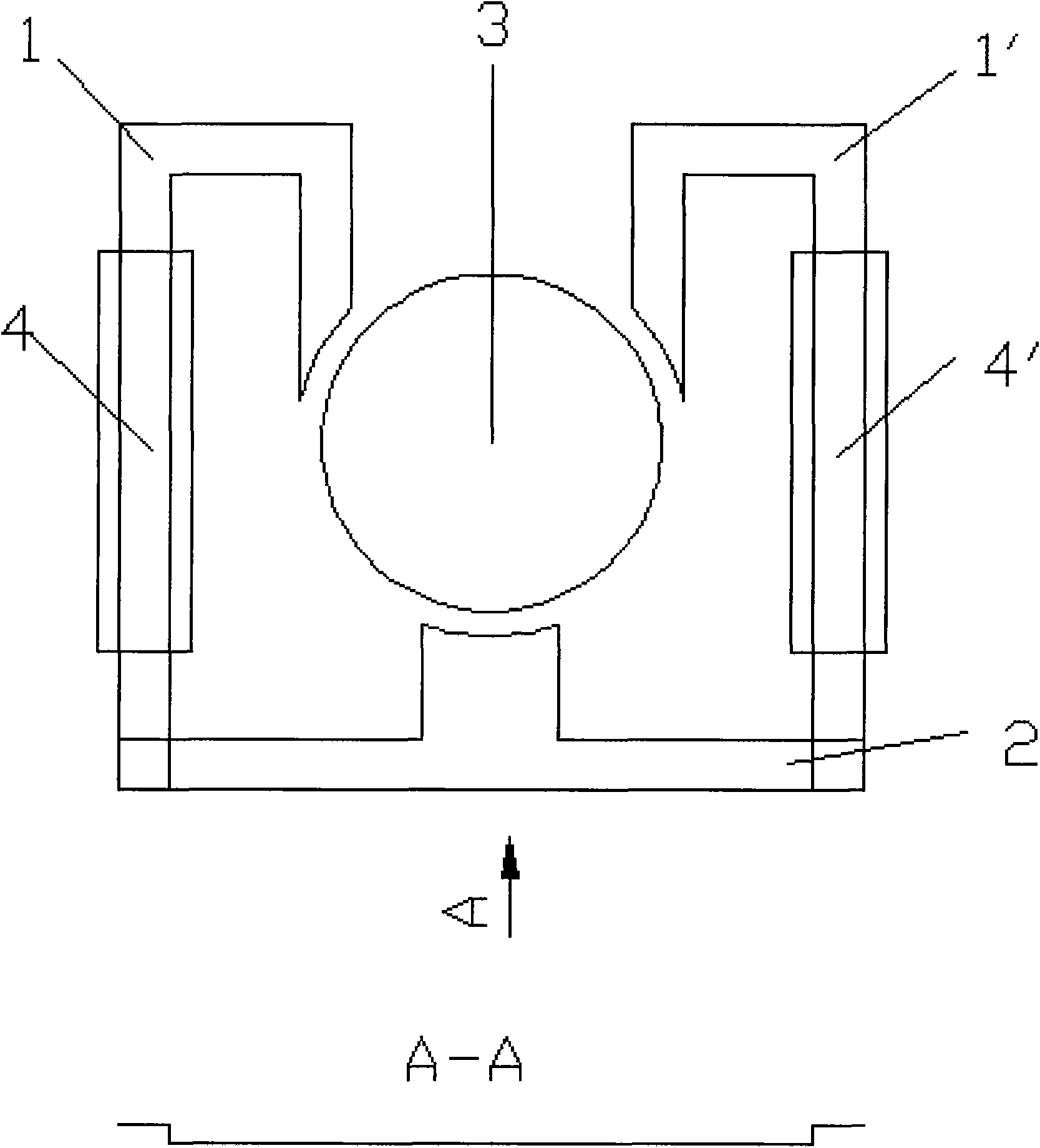
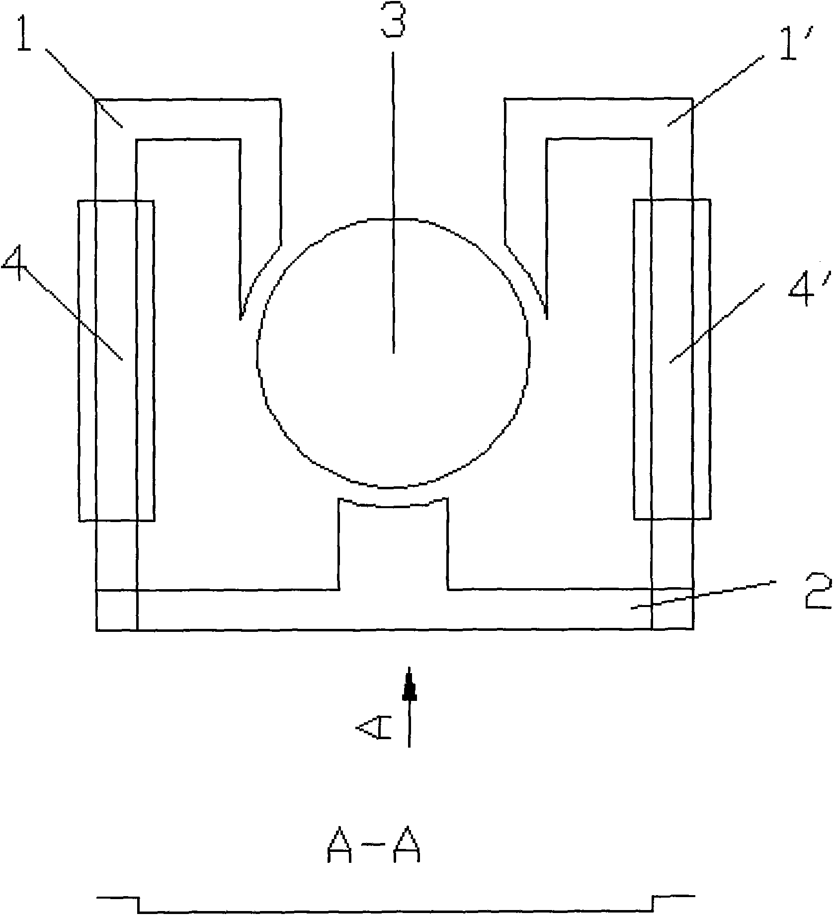
[0009] There are three stator slices: the first stator slice 1, the second stator slice 1`, and the third stator slice 2. One end surface of each stator piece is used as a magnetic pole surface, which is equally divided into 120° and distributed on the circumference. The other end of the first stator piece 1 passes through the stator coil 4 and is pressed against the third stator piece 2; the other end of the second stator piece 1` passes through the stator coil 4` and is pressed against the third stator piece 2, That is, the other end of the third stator piece 2 is separated by 180°, and is pressed against the first and second parts protruding from the stator coil. The third stator lamination is creased at the lap, see A-A. A magnet rotor 3 with a diameter of 5 to 8 mm is installed in the circumference, and the magnet rotor is radially filled with four pairs of magnetic poles.

[0010] When the external driving current enters the coil 4 and the coil 4 ′, the direction of th...


PUM


Abstract

The invention relates to an instrument step motor with a large rotor and low speed ratio. A core of an instrument comprises a stator, stator coils and a magnet rotor. The stator is made of a soft magnetic material and is divided into three pieces, one end face of each piece is used as a magnetic pole face, and the three pieces are distributed on the circumference at equal intervals by 120 DEG, wherein the other end of the first stator piece and the other end of the second stator piece respectively pass through the two stator coils to be overlapped with the third stator piece, i.e. the other end of the third stator piece is overlapped on the parts of the first stator piece and the second stator piece, stretching out of the stator coils, by being separated in 180 DEG. In order to solve the problem that three magnetic poles are not on the same plane because of overlapping, a folding mark of the third stator piece is processed in the overlapping position, and thus, the magnetic poles of the three stator pieces can be ensured to be on the same plane. The magnet rotor with 5-8 mm in diameter is assembled in the circumference and provided with four pairs of magnetic poles along the radial direction.

Description

technical field [0001] The invention relates to a movement of an instrument, which can be used to drive the deflection of pointers of automobiles and motorcycles by using the principle of a stepping motor to achieve the purpose of displaying numerical values. Background technique [0002] In the movement of automobile instrument, a kind of micro-stepping motor with high processing precision is used now. A kind of instrument stepper motor as disclosed in U.S. Patent 4,371,821. Among them, the stator sheet is very thin and easily twisted, which increases the difficulty of manufacture and assembly. The rotor of the motor has only one pair of magnetic poles, and the diameter is only about 2mm. This is very difficult to manufacture and requires a large reduction ratio to make the deflection speed of the pointer normal. For this reason, the number of teeth of the gear is increased, and the The difficulty of machining gears. Contents of the invention [0003] The purpose of th...

Claims


Application Information

Patent Timeline
Patent Type & Authority Applications(China)
IPC IPC(8): H02K37/04H02K37/14
Inventor 鱼运禄孙义质黄吉荣黄雪波
Owner 宁波九菱电机有限公司
Learn More