
High-voltage switch transfer current device

A technology for transferring current and high voltage, applied in high-voltage/high-current switches, high-voltage air circuit breakers, circuits, etc., can solve the problems of inability to protect the main contacts of the isolation switch effectively for a long time, adhesion, burning, etc. The effect of reducing arc voltage, suppressing movement, and increasing heat dissipation area

Inactive Publication Date: 2012-08-15
LIAONING YIDE IND GRP CO LTD
View PDF0 Cites 0 Cited by
  • Summary
  • Abstract
  • Description
  • Claims
  • Application Information

AI Technical Summary

Problems solved by technology

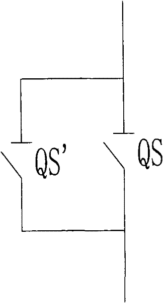
In order to solve this technical problem, one method is to install a set of auxiliary contacts in parallel on both sides of the main contact of the outdoor AC isolating switch to lead the arc to the auxiliary contacts, such as image 3 As shown, QS is the contact of the main isolating switch, and QS′ is the contact of the auxiliary isolating switch connected in parallel with the main isolating switch. The strong arc is drawn to the auxiliary contact to burn. Although this structure protects the main contact, the auxiliary contact Like the main contact, the head will also be burned and stuck, and cannot effectively protect the main contact of the isolating switch for a long time.

Method used


Image

  • High-voltage switch transfer current device
  • High-voltage switch transfer current device
  • High-voltage switch transfer current device

Examples


Embodiment Construction

[0014] The technical content of the patent application of the present invention will be described below in conjunction with the embodiments.

[0015] The structure of the high-voltage switching and transferring current device provided by the patent application of the present invention is shown in the accompanying drawings. The box 2 realizes both steering settings, and the steering square box 2 is fixedly installed on the switch control box 1 through an insulating neck tube. Such as Figure 5 and Figure 7 As shown, the static contact 5 and the moving contact 6 of the vacuum switch are coaxially arranged in the shielding cover 1 in the vacuum interrupter 4, the vacuum interrupter 4 is placed in the insulating tube, and the inner tube end of the insulating tube It is fixedly connected with the steering box 2 provided with an insulating outer layer; the front terminal board 7 is electrically conductive and fixedly installed on the outer end of the static contact 5 passing thro...


PUM


Abstract

The invention relates to a high-voltage, ultrahigh-voltage and extra-high voltage switch transfer current device for busbar transfer load current operation. The high-voltage switch transfer current device comprises a horizontally arranged vacuum switch, a switch operating box and a steering square box between the horizontally arranged vacuum switch and the switch operating box, wherein a fixed contact and a moving contact of the vacuum switch are coaxially arranged opposite to each other in a shielding case of a vacuum arc extinction chamber, a plurality of thread grooves are arranged on a columnar contact of the fixed contact from the columnar face to the end face of the contact at equal intervals, and the contact end of the moving contact is provided with a slot matched with the columnar contact of the fixed contact; a brake separating spring crank arm, a braking crank arm and a roller crank arm are arranged on a control main shaft of an operating mechanism of the switch operating box. By the technical scheme, an isolating switch is endowed with the capability of switching on and off busbar transfer current during double-busbar changeover operation, and thus, the technical purpose that power-frequency low-voltage great-current transfer current arcs produced in the busbar transfer can be switched on and off by the moving contact and the fixed contact of a 100-1100 KV outdoor AC high-voltage isolating switch can be achived.

Description

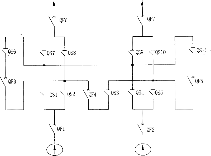
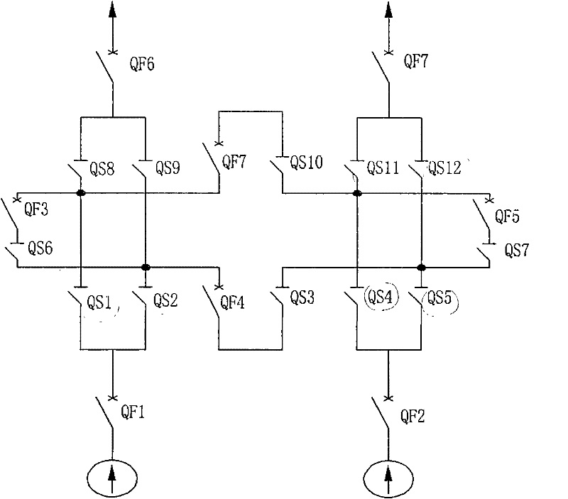
technical field [0001] The patent application of the present invention relates to a high-voltage, ultra-high-voltage and ultra-high-voltage switching transfer current device that cooperates with a 110-1100KV outdoor AC high-voltage isolating switch to realize arc-free breaking of the outdoor AC high-voltage isolating switch and achieve busbar conversion load current operation. Background technique [0002] my country's national standard GB1985-2004 "High Voltage AC Isolating Switch and Grounding Switch" clearly stipulates that the isolating switch in the operating position of the double-bus inverted busbar must have the ability to open and close the busbar to transfer current. For example figure 1 and figure 2 In the double-bus single-section system and double-bus double-section system shown, the outdoor AC high-voltage isolation switches QS1, QS2, QS4, QS5, QS8, QS9, QS11, and QS12 are all 110-1100KV outdoor AC high-voltage isolation switches. All need to have the abilit...

Claims


Application Information

Patent Timeline
Patent Type & Authority Patents(China)
IPC IPC(8): H01H33/66H01H33/666
Inventor 杜玉乐钟启辉于鹤田
Owner LIAONING YIDE IND GRP CO LTD
Learn More