
Energy-conserving drying device

A drying device, energy-saving technology, applied in drying, dryer, drying gas layout and other directions, can solve the problems of not more accurate utilization, differentiated treatment, energy waste, etc., to save energy, reduce heat loss, The effect of improving product quality

Inactive Publication Date: 2011-02-02
武汉宇恩防伪技术有限公司
View PDF9 Cites 23 Cited by
  • Summary
  • Abstract
  • Description
  • Claims
  • Application Information

AI Technical Summary

Problems solved by technology

[0002] At present, many equipment need to be dried after the parts are processed, so drying is also a necessary process in many processes, so the drying device is also a device that is often included in many devices. In the existing drying device, Various methods are often used for heating and drying, such as steam heating for drying, and electric heating for drying. In the drying process, the existing equipment usually uses outdoor fresh air to send air to the drying room, and then the The exhaust gas containing volatile solvents in the drying room is discharged. When these high-temperature exhaust gases are discharged, a large amount of heat energy is taken away, resulting in a waste of energy. There are often multi-stage ovens on the drying device, and the fresh air is heated to a high temperature by an electric heater. The air is used to dry the workpiece in sections. The temperature of each oven can be the same or different according to the process requirements. Each oven has an air inlet duct and an exhaust duct, so a large amount of fresh air is just heated into hot air. Directly discharged from the drying room, that is, a large amount of heat energy is discharged to cause a great waste of energy, especially in mass production and production with multiple equipment. Such waste is very amazing; engineers and technicians have also found that this waste is Seriously, research has been carried out in this area, and the existing problems have been found out: uniform mixing of high and low temperatures, unified overall discharge, no different treatment for the specific conditions of different sections, different use of exhaust gas, and no more accurate use of air volume and The relationship between drying, the relationship between exhaust gas concentration and drying, and the possibility of internal circulation to reduce energy consumption, etc., these issues need to be further studied and solved in order to develop a more reasonable and energy-saving drying device

Method used


Image

  • Energy-conserving drying device
  • Energy-conserving drying device
  • Energy-conserving drying device

Examples


Embodiment Construction

[0035] The present invention will be further introduced below in conjunction with the accompanying drawings and specific embodiments, but not as a limitation of the present invention.

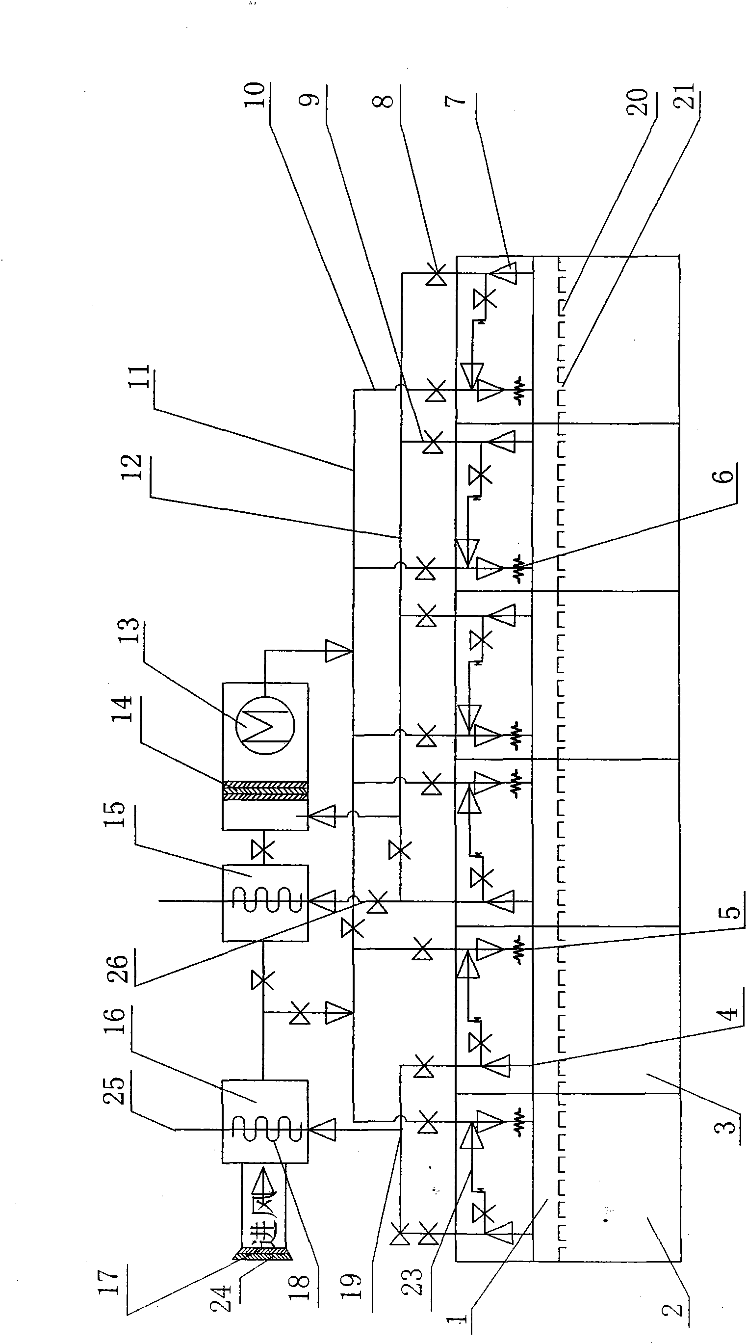
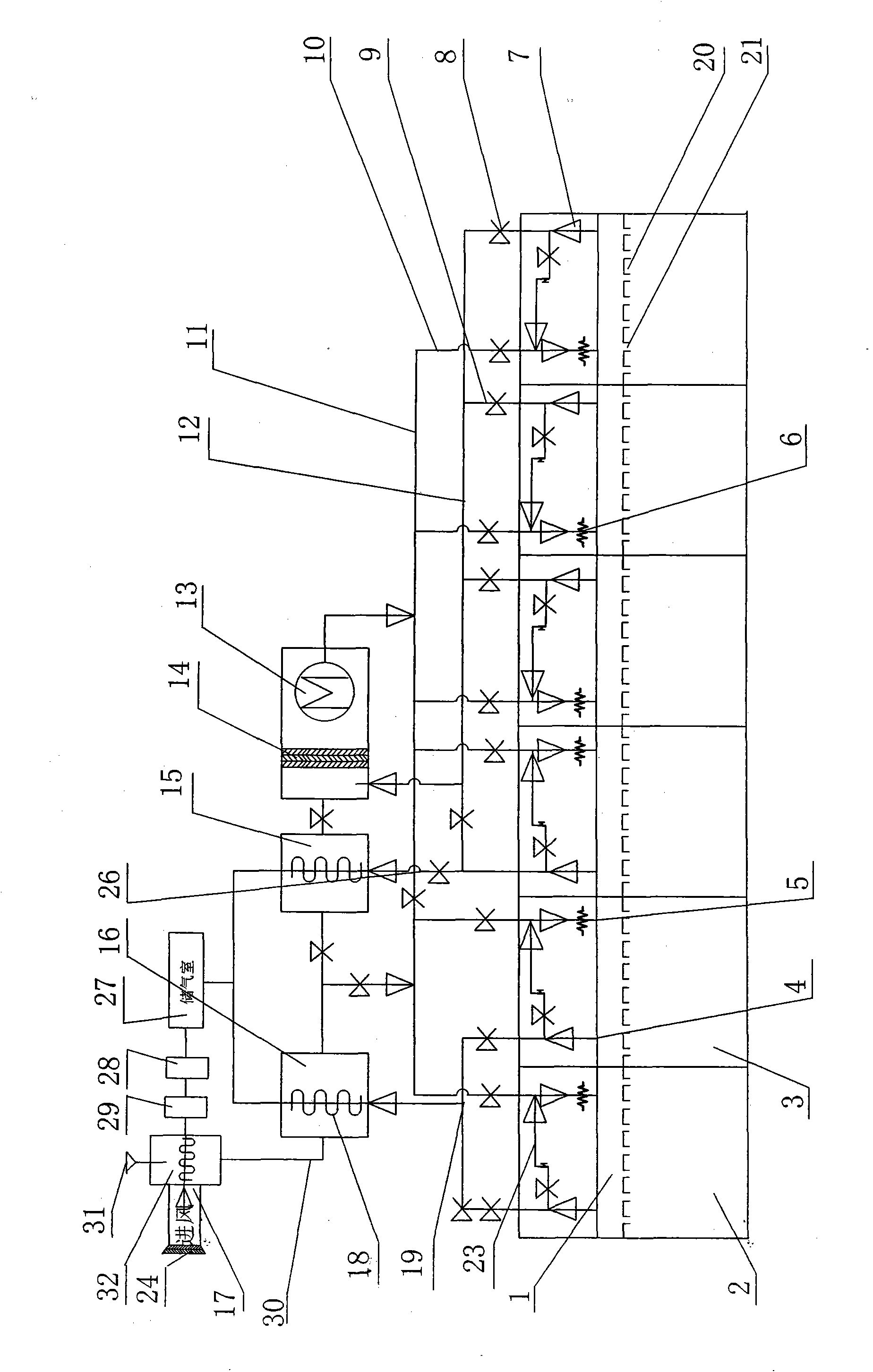
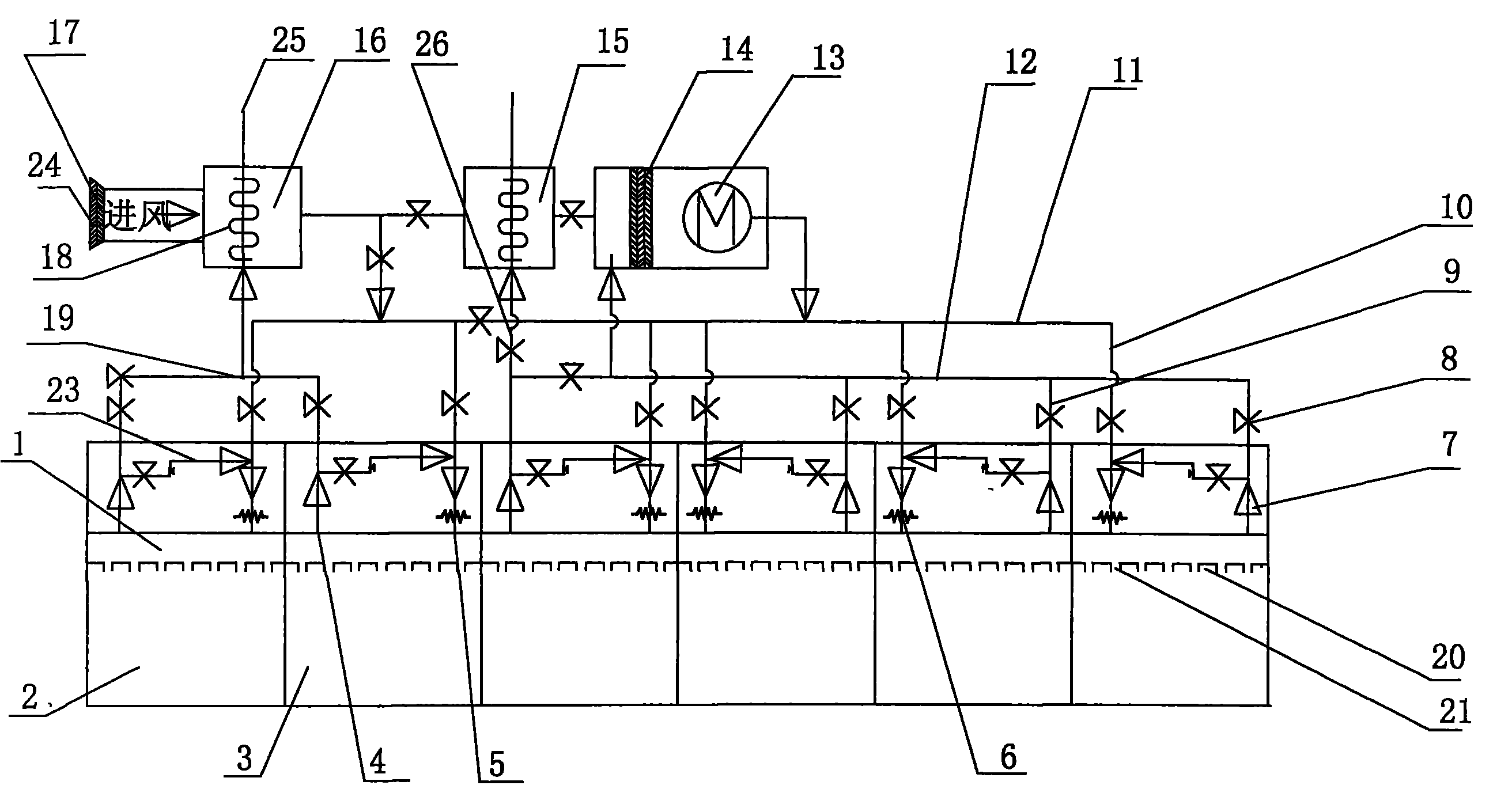
[0036] Such as figure 1 As shown, an embodiment of an energy-saving drying device of the present invention, in figure 1Among them, an energy-saving drying device, including: drying chamber 2, drying products is an important and indispensable process, and the various coatings used in these products usually contain volatile substances, which are sent into the drying chamber. The products in the drying chamber 2 are sequentially entered into each oven 3 by a conveyor (not shown in the figure) for drying and then flow into the next process. 17 After the air is taken, the fresh air is heated to a high-temperature gas through a heat exchanger. If the temperature does not meet the requirements, there is an electric heater 6 at the air inlet for supplementary heating. The heated hot air divides the co...


PUM


Abstract

The patent refers to the field of 'drying solid materials or objects by removing liquid therefrom'. The invention relates to a drying device, particularly relating to an energy-conserving device, and providing a high-air-volume multistage circular energy-conserving drying device utilizing wastes to heat fresh air. A drying room is composed of multi-section drying ovens; each drying oven is provided with a diaphragm; an enclosed air room with multiple air flue slits is arranged on the diaphragm, and is communicated with a heat exchanger through an air inlet main pipe, an air inlet branch pipe, an air outlet main pipe and an air outlet branch pipe; a fresh-air taking opening is connected with the heat exchanger and a heat exchanging draught fan in sequence; the outlet of the heat exchanger, the air inlet main pipe and the air inlet branch pipe are connected with each air room; the air exhaust branch pipe of the previous two-section drying oven air room with high waste gas concentration is discharged through a primary heat exchanger; other air exhaust branch pipes are connected on the air outlet branch pipe, and are connected with a secondary heat exchanger and the front end part of the heat exchanging draught fan to form circulation; the inner air volume is increased; the hot air circulates in the drying oven; the waste gas temperature is utilized to save energy source; the drying oven temperature is flexibly set, and small circulation is flexibly regulated in the drying oven; and the temperature control is uniform.

Description

technical field [0001] The invention relates to a drying device, in particular to an energy-saving drying device. Background technique [0002] At present, many equipment need to be dried after the parts are processed, so drying is also a necessary process in many processes, so the drying device is also a device that is often included in many devices. In the existing drying device, Various methods are often used for heating and drying, such as steam heating for drying, and electric heating for drying. In the drying process, the existing equipment usually uses outdoor fresh air to send air to the drying room, and then the The exhaust gas containing volatile solvents in the drying room is discharged. When these high-temperature exhaust gases are discharged, a large amount of heat energy is taken away, resulting in a waste of energy. There are often multi-stage ovens on the drying device, and the fresh air is heated to a high temperature by an electric heater. The air is used ...

Claims


Application Information

Patent Timeline
Patent Type & Authority Applications(China)
IPC IPC(8): B05D3/02F26B15/12F26B21/00
Inventor 汪俊熊飞虎聂犇刘子虎刘兵王智斌
Owner 武汉宇恩防伪技术有限公司
Learn More