Vehicle coupler capable of preventing automatic locking

An automatic locking and coupler technology, which is applied in the field of couplers, can solve problems such as breaking the balance of torque, unfavorable truck transportation management, and inconvenient shunting operations, achieving low cost, reducing automatic locking phenomena, and improving efficiency.

Active Publication Date: 2011-02-02
CRRC MEISHAN
View PDF5 Cites 4 Cited by
  • Summary
  • Abstract
  • Description
  • Claims
  • Application Information

AI Technical Summary

Problems solved by technology

However, when the speed of most of the vehicles exceeds 4km / h, when the vehicle is connected to the front train, the rear coupler is under the instantaneous impact, and the torque generated by the speed exceeds the torque between the knuckle and each part. The sum of the frictional moments breaks the moment balance of the knuckle around the knuckle pin, so that the rear end of the knuckle rotates, so that the coupler is automatically locked, such as image 3 As shown, it is a schematic diagram of the automatic locking of the rear-end coupler when the vehicle is connected, which makes it impossible to realize the connection again
In this way, after the slipping vehicle is linked and merged into the next train, the rear-end coupler is automatically locked, if it is to be slipped again to realize the connection, the operator must go back and forth to open the automatically locked coupler to the fully open position. , thus bringing inconvenience to the shunting operation, resulting in lower shunting operation efficiency, which is not conducive to improving the management of truck transportation

Method used


Image

  • Vehicle coupler capable of preventing automatic locking
  • Vehicle coupler capable of preventing automatic locking
  • Vehicle coupler capable of preventing automatic locking

Examples


Embodiment Construction

[0022] Below in conjunction with accompanying drawing, the present invention is described in detail.

[0023] In order to make the object, technical solution and advantages of the present invention clearer, the present invention will be further described in detail below in conjunction with the accompanying drawings and embodiments. It should be understood that the specific embodiments described here are only used to explain the present invention, not to limit the present invention.

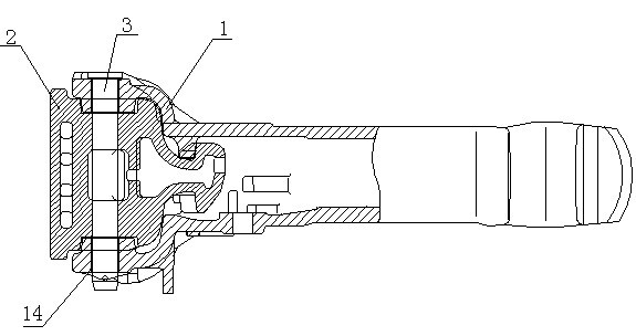
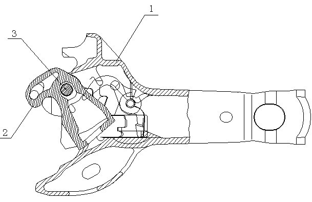
[0024] Such as Figures 4 to 9 As shown, a coupler that can prevent automatic locking includes a coupler body 1, a knuckle tongue 2 and a knuckle pin 3. The hook body 1 is hinged, and an elastic member 5 is arranged in the inner cavity of the knuckle 2, and the elastic member 5 is a leaf spring with a thickness of 1.5 mm to 4.5 mm; at the top flange position of the knuckle pin 3 An orientation plate 11 is fixedly connected. After the knuckle pin 3 is inserted into the knuckle pin hole 4, the ori...


PUM


Abstract

The invention discloses a vehicle coupler capable of preventing automatic locking, which comprises a coupler body, a coupler knuckle and a coupler knuckle pin. The coupler knuckle is articulated with the coupler body through the coupler knuckle pin arranged in a coupler knuckle pin hole of the coupler body, an elastic component is arranged in a cavity of the coupler knuckle, and the coupler knuckle pin and the coupler body are relatively fixed. Two plane sections are processed on the curved surface of the coupler knuckle pin, and a relatively protruding transition section is formed between the two plane sections. The head part of the elastic component is tightly attached to the plane sections after being bent toward the S face of the coupler knuckle, the tail part and the coupler knuckle are relatively fixed, and the folding point between the head part and the middle part of the elastic component is supported by a protrusion in the cavity of the coupler knuckle. An external force required for changing the vehicle coupler from the full open state to a locking state is effectively increased under the premise of not influencing the use performance of the traditional vehicle coupler assembly, the automatic locking phenomenon of coupler knuckle rotation caused by impact during coupling of a back-end vehicle coupler in vehicle rolling is greatly reduced, and thus, the efficiency of railway vehicle shunting work is increased.

Description

technical field [0001] The invention relates to a coupler which prevents automatic locking when trains are connected during the hump rolling operation process of railway freight car vehicle dispatching. Background technique [0002] The coupler is a key part of the connecting part of the railway wagon. At present, the coupler assembled on the new wagon and the wagon running on the line, such as figure 1 and 2 As shown, it mainly includes a hook body 1, a knuckle tongue 2 and a knuckle pin 3. The knuckle pin 3 can rotate relative to the hook body 1 and the knuckle tongue 2 only by overcoming the friction force, and the knuckle 2 is unlocked around the knuckle pin 3. , When locking and rotating, it is only necessary to overcome the frictional force between the knuckle 2 and each part. [0003] In actual operation, truck transportation management is usually accompanied by the marshalling and dispatching of a large number of vehicles. In the process of vehicle dispatching, wh...

Claims


Application Information

Patent Timeline
Patent Type & Authority Applications(China)
IPC IPC(8): B61G1/00
Inventor 李竹肖颖刘文中徐五一刘成勇王之成安磊杨晓明袁永宏余汝松刘幼平
Owner CRRC MEISHAN
Why Eureka
Try Eureka