High-frequency rotary connector

A rotary connector, high-frequency technology, applied in the direction of connection, two-part connection device, parts of the connection device, etc., can solve problems such as distortion of the transmission signal of the slip ring, and achieve a simple and reasonable structure, low cost, and solve serious distortion. Effect

Inactive Publication Date: 2011-01-26
杭州全盛机电科技有限公司
View PDF4 Cites 3 Cited by
  • Summary
  • Abstract
  • Description
  • Claims
  • Application Information

AI Technical Summary

Problems solved by technology

[0005] The problem to be solved by the present invention is the technical problem of signal transmission in the rotating body. The traditional slip ring is seriously distorted when transmitting the signal. At the same time, it provides an easy-to-manufacture and economical slip ring system

Method used


Image

  • High-frequency rotary connector
  • High-frequency rotary connector
  • High-frequency rotary connector

Examples


Embodiment Construction

[0018] The present invention will be further described below in conjunction with the accompanying drawings and implementation examples.

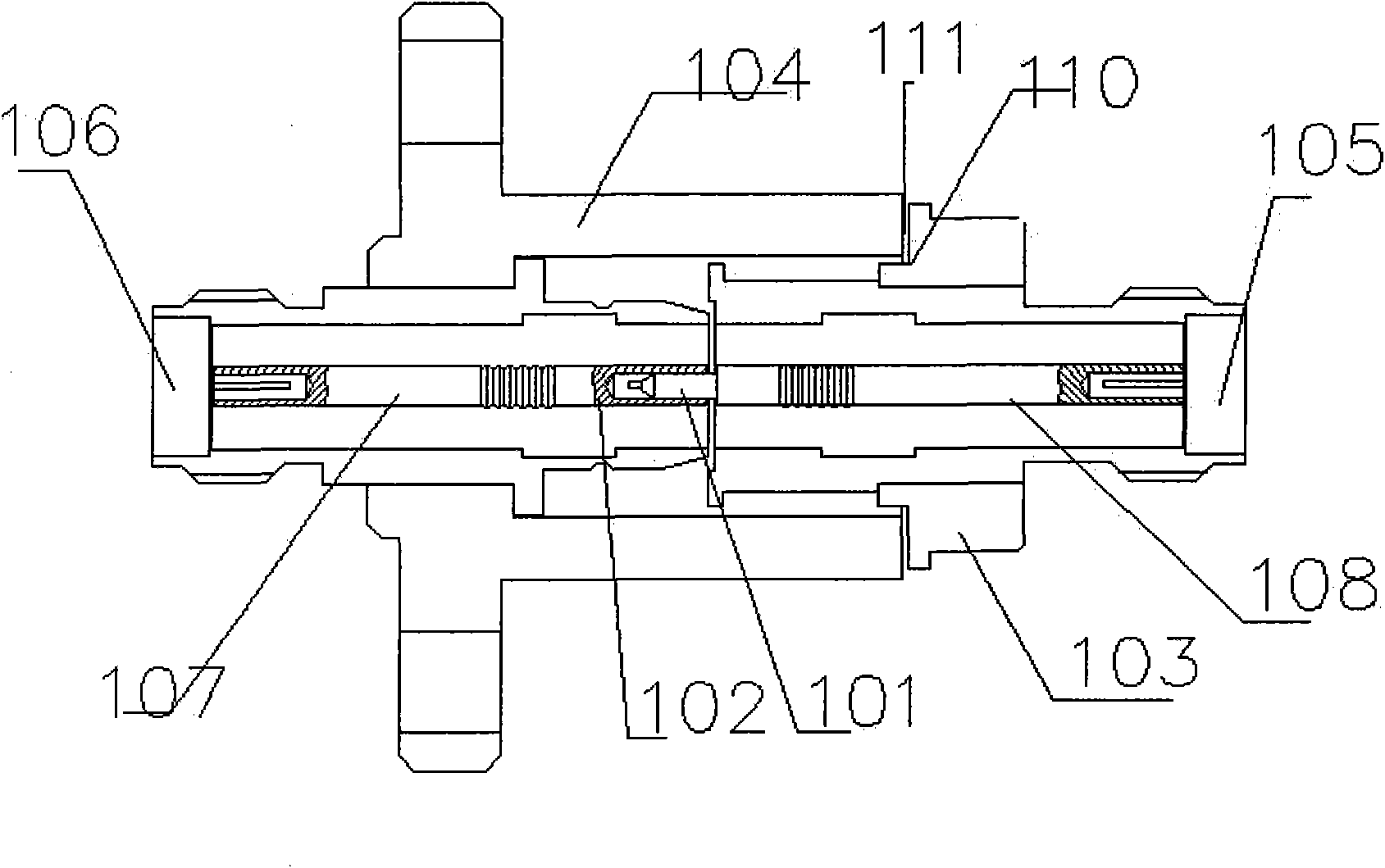
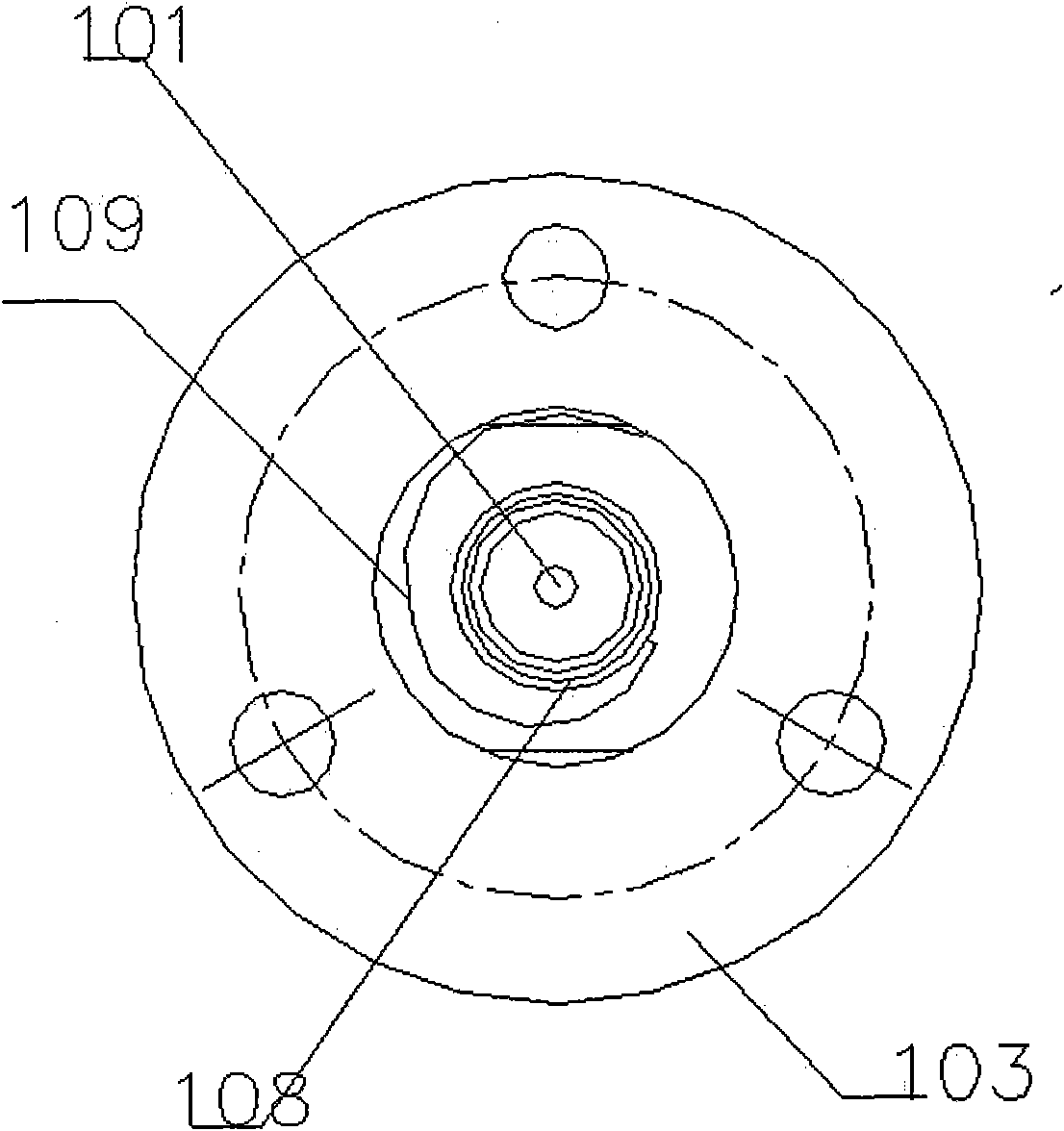
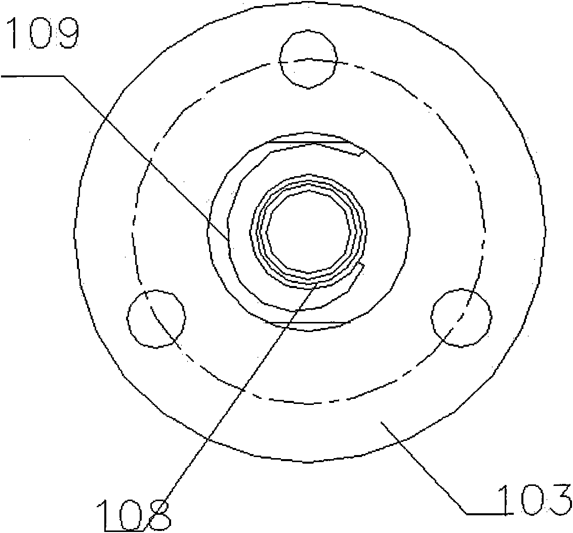
[0019] A high-frequency rotary connector consists of 101-rotor top shaft; 102-stator groove; 103-rotor shell; 104-stator shell; 105-rotor SAM card slot; 106-stator SAM slot; 107-stator inner shaft 108-rotor inner shaft; 109-rolling connection device; 110-rotor shell notch; 111-stator shell convex.

[0020] Connect the fixed equipment signal transmission line socket to the 106-stator SAM slot, and the signal is transmitted to the 107-stator inner shaft and to the 102-stator groove through the 109-rolling connection device to 101 with the 109-rolling connection device -Rotor top shaft, the signal is transmitted to 101-rotor top shaft and connected to 108-rotor inner shaft, 108-rotor inner shaft is connected to 106-stator SAM slot, 106-stator SAM slot is connected to the rotating body, the signal is It is transferred from the fixed device to t...


PUM


Abstract

The invention discloses a high-frequency rotary connector, which consists of two parts, namely a rotor part and a stator part, wherein the stator part consists of a stator groove, a stator shell, a stator SAM slot, a stator inner shaft and a convex opening of the stator shell; and the rotor part consists of a rotor top shaft, a rotor shell, a rotor SAM card slot, a rotor inner shaft, a rolling connection device and a concave opening of the rotor shell. Due to sliding connection of the stator groove, the rotor top shaft and the rolling connection device, the high-frequency rotary connector avoids a signal transmission distortion phenomenon under high-speed operation through the formed closed connection. The high-frequency rotary connector has the advantages that: the device effectively solves the problem of serious distortion during signal transmission in the signal transmission process and has the advantages of simple and reasonable structure and lower cost.

Description

【Technical field】 [0001] The invention relates to an electrical component that communicates with a rotating body and transmits energy and signals, and in particular relates to the technical field of a high-frequency rotary connector. 【Background technique】 [0002] As we all know, in modern times, in the high-end field of industrial equipment, there are many requirements for multiple relative motions such as revolution and rotation. That is, while the mechanical equipment rotates continuously at 360°, multiple motions are required on the rotating body. If there is movement, energy is needed, such as electric energy, fluid pressure energy, etc. Sometimes, it is also necessary to control the signal source, such as optical fiber signal, high frequency signal, etc. Any electromechanical equipment that needs to transmit functional power, weak electrical signals, optical signals, air pressure, water pressure, oil pressure and other energy media between electrical components that...

Claims


Application Information

Patent Timeline
Patent Type & Authority Applications(China)
IPC IPC(8): H01R24/02H01R13/646
Inventor 刘益清
Owner 杭州全盛机电科技有限公司
Why Eureka
Try Eureka