
Liquid crystal display panel and manufacturing method thereof

A technology for liquid crystal display panels and manufacturing methods, applied in nonlinear optics, instruments, optics, etc., capable of solving problems such as liquid crystal pollution, affecting the arrangement and deflection of liquid crystal molecules, and affecting the quality of liquid crystal display panels, so as to avoid pollution and improve quality Effect

Inactive Publication Date: 2011-01-26
BEIJING BOE OPTOELECTRONCIS TECH CO LTD
View PDF0 Cites 24 Cited by
  • Summary
  • Abstract
  • Description
  • Claims
  • Application Information

AI Technical Summary

Problems solved by technology

[0004] For the liquid crystal display panel provided by the above-mentioned prior art, after the cell alignment process and before the curing treatment, if the amount of liquid crystal is too large or the liquid crystal expands due to heat, the liquid crystal will be in contact with the sealant, and the viscosity of the liquid crystal will decrease. , the speed of liquid crystal diffusion is getting faster and faster. Under certain conditions, the liquid crystal and the uncured sealant are prone to interact, which affects the alignment and deflection of the liquid crystal molecules, thereby causing liquid crystal pollution, which in turn affects the quality of the liquid crystal display panel.

Method used


Image

  • Liquid crystal display panel and manufacturing method thereof
  • Liquid crystal display panel and manufacturing method thereof
  • Liquid crystal display panel and manufacturing method thereof

Examples


Embodiment Construction

[0016] The technical solutions of the present invention will be described in further detail below with reference to the accompanying drawings and embodiments.

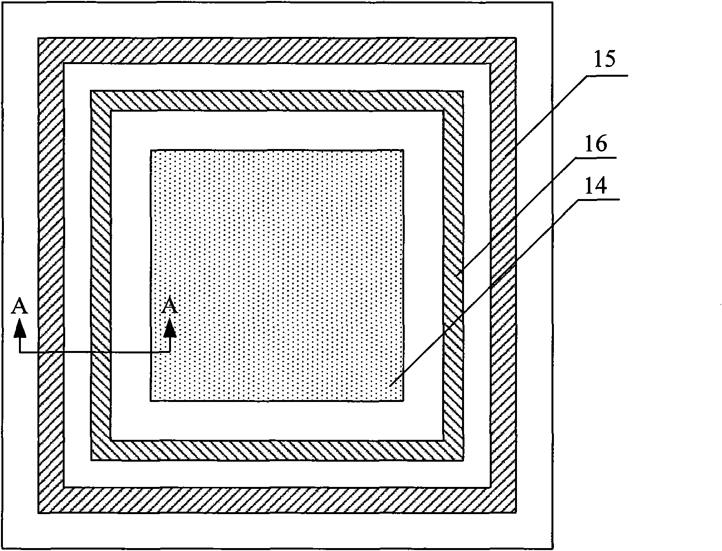
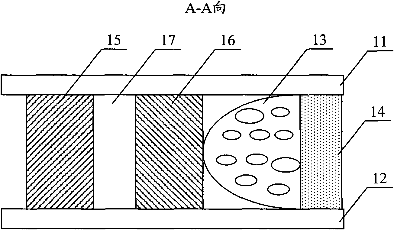
[0017] figure 1 It is a top view schematic diagram of an embodiment structure of the liquid crystal display panel of the present invention, figure 2 for figure 1 A cross-sectional view in the direction of A-A. Such as figure 1 and figure 2 As shown, this embodiment includes a first substrate and a second substrate oppositely arranged, wherein the first substrate is specifically the color filter substrate 11 , and the second substrate is specifically the array substrate 12 . The space between the color filter substrate 11 and the array substrate 12 is filled with liquid crystals 13, and the display area 14 of the color filter substrate 11 and the array substrate 12 is surrounded by an outer sealant 15, which is used to seal the two substrates together. . In this embodiment, an inner layer sealant 16 is provided ...


PUM

PropertyMeasurementUnit
widthaaaaaaaaaa
widthaaaaaaaaaa

Abstract

The invention relates to a liquid crystal display panel and a manufacturing method thereof. The liquid crystal display panel comprises a first substrate and a second substrate oppositely arranged; liquid crystal is filled between the first substrate and the second substrate; and an outer-layer frame sealing adhesive is arranged at the periphery of a display area of the first and second substrates and is used for sealing the two substrates, wherein an inner-layer frame sealing adhesive is arranged between the edge of the display area and the outer-layer frame sealing adhesive, and is a cured frame sealing adhesive before the first substrate and the second substrate are combined. The inner-layer frame sealing adhesive is arranged between the edge of the display area and the outer-layer frame sealing adhesive, and can effectively prevent the liquid crystal from being contacted with the outer-layer frame sealing adhesive; and the inner-layer frame sealing adhesive is the cured frame sealing adhesive before the first substrate and the second substrate are combined, so the inner-layer frame sealing adhesive is difficult to react with the liquid crystal to avoid polluting the liquid crystal and further improve the quality of the liquid crystal display panel.

Description

technical field [0001] The invention relates to the field of liquid crystal display manufacturing, in particular to a liquid crystal display panel and a manufacturing method thereof. Background technique [0002] With the advancement of liquid crystal display technology, the requirements for the quality of liquid crystal display panels are getting higher and higher, and more and more high-quality liquid crystal displays are coming to the market gradually, and many problems have also appeared at the same time. [0003] A liquid crystal display panel in the prior art includes a color filter substrate, an array substrate, and spacers arranged between the color filter substrate and the array substrate, and liquid crystals are filled between the color filter substrate and the array substrate, and the color filter substrate and the array substrate There is a frame sealant around the display area to seal the two substrates. The manufacturing process of the liquid crystal display p...

Claims


Application Information

Patent Timeline
Patent Type & Authority Applications(China)
IPC IPC(8): G02F1/1333G02F1/1339
Inventor 车春城
Owner BEIJING BOE OPTOELECTRONCIS TECH CO LTD
Learn More