
Composite optical film

A technology of optical film and light-concentrating layer, which is applied in the field of composite optical film, can solve the problems of not conforming to the trend of light and thin, increasing the thickness of the backlight module, and the complexity of the backlight module, etc., to achieve the effect of increasing light utilization efficiency, easy assembly, and thin thickness

Inactive Publication Date: 2011-01-26
ETERNAL MATERIALS CO LTD
View PDF4 Cites 15 Cited by
  • Summary
  • Abstract
  • Description
  • Claims
  • Application Information

AI Technical Summary

Problems solved by technology

[0003] In order to solve the above problems, the current method used in the industry is to add a protective diffusion film (or called top diffuser film) to improve the above optical phenomenon, but the disadvantage is that the price of this top diffuser film (top diffuser) is too expensive and increases An optical film will increase the thickness of the backlight module and make the backlight module more complicated, which does not conform to the trend of light and thin

Method used


Image

  • Composite optical film
  • Composite optical film
  • Composite optical film

Examples


preparation example Construction

[0081] Preparation of composite optical film of the present invention

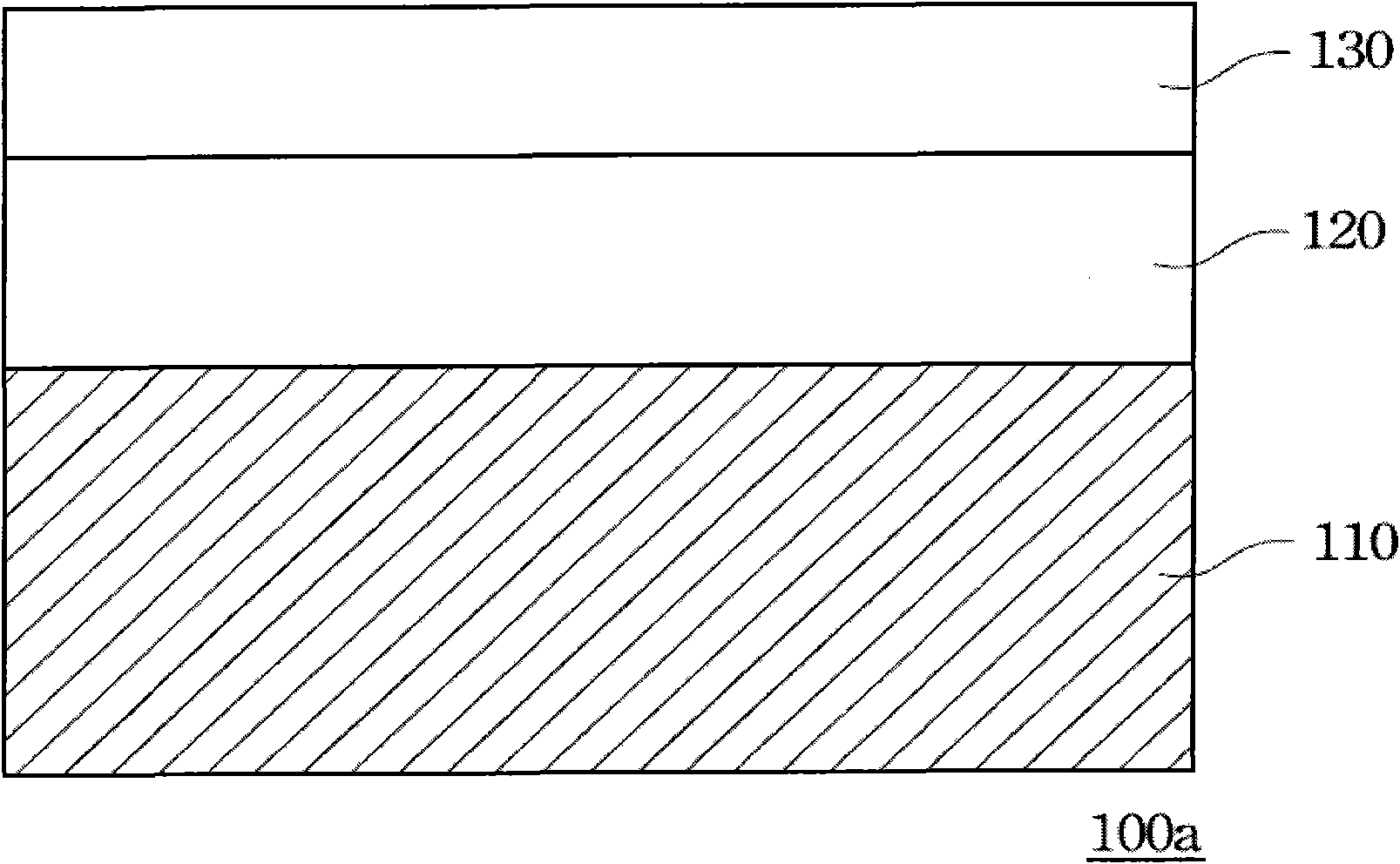
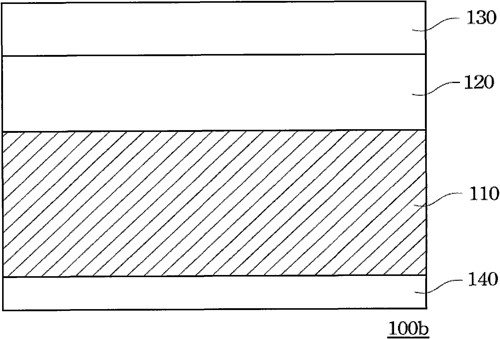
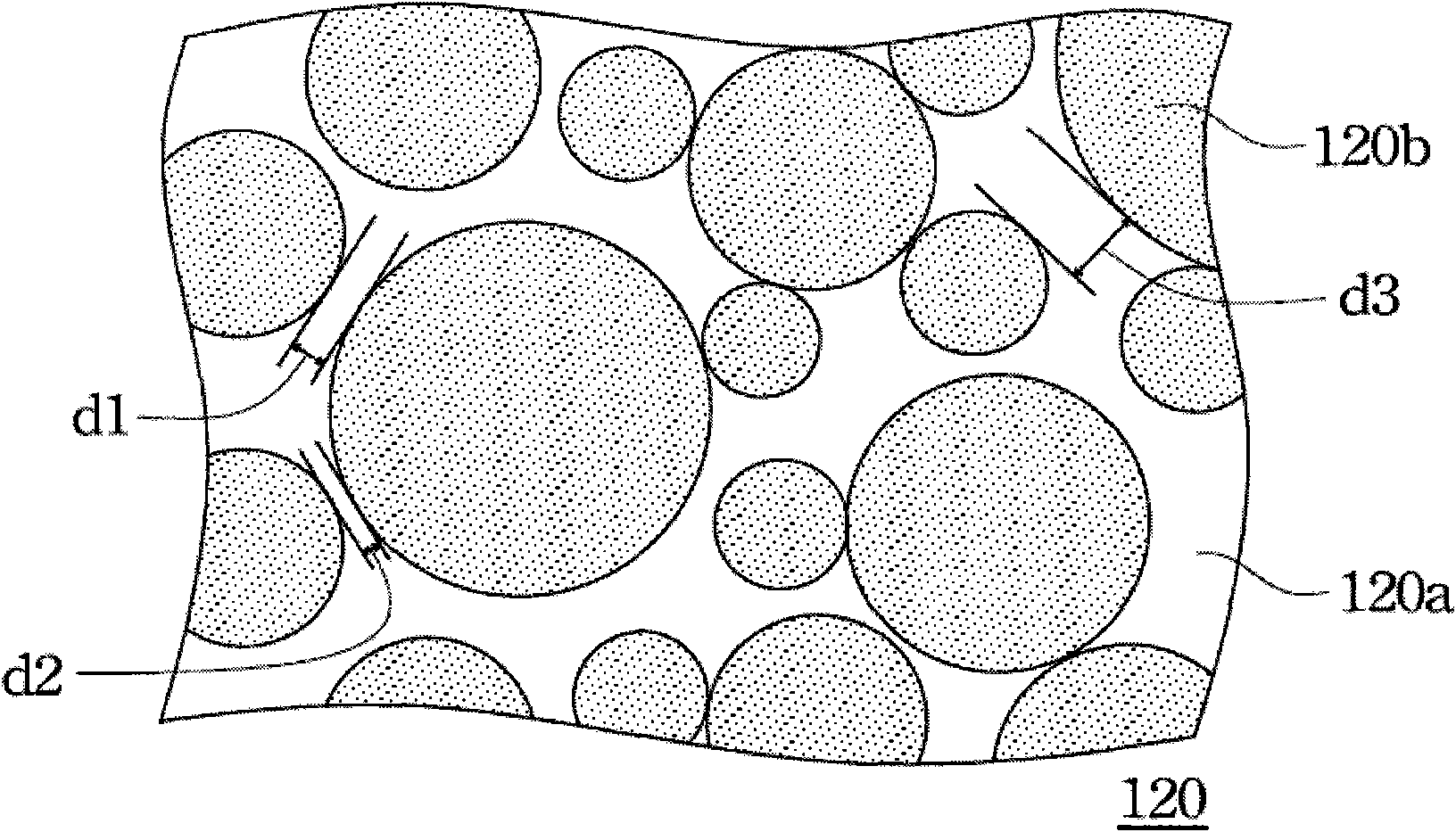
[0082] Firstly, the light diffusion layer 120 is formed on the base material 110 by coating, spraying or pasting. Taking coating as an example, the coating containing the micro-beads 120 b and the bonding agent 120 a can be coated on the substrate 110 . There is no particular limitation on the number of times of coating in the above-mentioned coating method, and it can be applied once or multiple times. Among them, multiple coatings can utilize a little fluidity before the paint is dry, so that the micro-beads 120b on the upper layer fill the depressions formed between the micro-beads 120b on the lower layer, so as to improve the tightness of the arrangement of the micro-beads 120b , the thickness of the light diffusion layer 120 can also be increased.

[0083] Next, the light-gathering layer 130 is formed on the light-diffusing layer 120, and the formation method can be direct lamination or coating. The...

specific Embodiment

[0085] like image 3 ,for Figure 1A The cross-sectional structure schematic diagram of the specific embodiment.

[0086] exist image 3 Among them, the composite optical film 300 a has a substrate 310 , a light diffusing layer 320 and a light concentrating layer 330 in sequence from bottom to top. The light-diffusing layer 320 is composed of a coating having a concave-convex microstructure, and the average thickness of the light-diffusing layer 320 is H. The coating material of the light diffusion layer 320 contains a bonding agent 320a and microbeads 320b.

[0087] The light concentrating layer 330 on the light diffusing layer 320 has a plurality of prism columnar structures 330a, which can be used as light concentrating microstructures. The distance between adjacent prism columnar structures 330a is D, and the apex angle thereof is 40°-120°. The forming method of the prism columnar structure 330a may be slit die coating, micro gravure coating or roller coating. The resin...


PUM

PropertyMeasurementUnit
particle sizeaaaaaaaaaa
thicknessaaaaaaaaaa

Abstract

The invention provides a composite optical film, comprising a substrate, a light diffusion layer allocated on the substrate and a light concentration layer located on the light diffusion layer. The light diffusion layer comprises at least one microsphere and a jointing compound, the thickness of the light diffusion layer is 2-6 times the average particle size of the microsphere, and the distance between adjacent microspheres is smaller than the average particle size of the microsphere; and the light concentration layer is provided with at least one light contration microstructure. The composite optical film has favorable diffusion and light concentration functions, can effectively eliminate a Newton ring, not only can effectively enhance light ray application efficiency, but also has smaller thickness so as to ensure that the backlight module is easier to assemble.

Description

technical field [0001] The invention relates to a composite optical film, in particular to a composite optical film applied to a liquid crystal display. Background technique [0002] The main structure of a general liquid crystal display (Liquid Crystal Display; LCD) includes two parts: a panel and a backlight module. The backlight module used as the light source of the liquid crystal display further includes a point light source (such as a light emitting diode) or a line light source (such as a lamp tube), a light guide plate, and various optical films. Among the various components of the backlight module, the power consumption and heat generation of the point light source or line light source are the most. Therefore, in order to maintain or even increase the brightness of the liquid crystal display, how to reduce the power consumption and heat generation of point light sources or line light sources has become an important issue. At present, various optical films are used...

Claims


Application Information

Patent Timeline
Patent Type & Authority Applications(China)
IPC IPC(8): G02B5/02G02B5/04G02B1/10G02F1/13357B32B5/16
Inventor 汪宗兴林博文汪乙嘉胡瑞楷
Owner ETERNAL MATERIALS CO LTD
Learn More