Vacuum transmission pipe and connecting structure thereof

A vacuum transmission and vacuuming technology, which is applied in the direction of flange connection, sealing surface connection, pipe/pipe joint/pipe fitting, etc., can solve the problems of thick heat transfer pipe and unsatisfactory heat transfer effect, and achieve good and good heat preservation effect Thermal insulation effect, effect of preventing heat leakage

Active Publication Date: 2012-10-31
湖北贵族真空科技股份有限公司
View PDF0 Cites 0 Cited by
  • Summary
  • Abstract
  • Description
  • Claims
  • Application Information

AI Technical Summary

Problems solved by technology

[0002] Heat transfer pipe is a pipe widely used in solar power generation, heating and chemical industry. Existing heat transfer pipes generally wrap one or more layers of insulation materials on the outer surface of ordinary pipes. In the field of solar power generation, heat transfer is required The tube has a good thermal insulation effect, so it is necessary to wrap multiple layers of thermal insulation material on the outer surface of the ordinary tube, resulting in a thicker heat transfer tube, and the heat transfer effect is not ideal

Method used


Image

  • Vacuum transmission pipe and connecting structure thereof
  • Vacuum transmission pipe and connecting structure thereof
  • Vacuum transmission pipe and connecting structure thereof

Examples


Embodiment 1

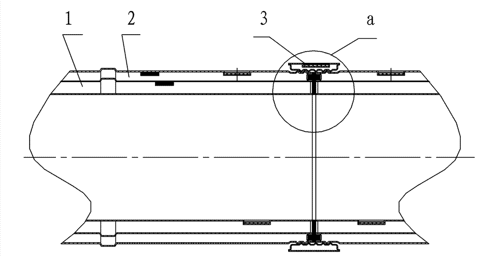
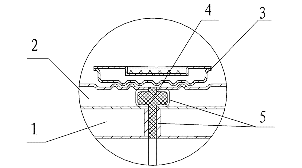
[0020] Embodiment 1: This embodiment is a double-layer vacuum heat insulation pipe composed of three layers of pipes. The inner layer vacuum heat insulation pipe 1 is vacuumized between the inner layer pipe and the middle layer pipe, and the vacuum heat insulation pipe 1 is between the outer layer pipe and the middle layer pipe. Vacuum outer layer vacuum heat insulation pipe 2, two adjacent vacuum transmission pipes are connected by a connecting piece in the axial direction, the connecting piece is composed of a collar 3 and a sealing piece 4, and the collar 3 is vacuum insulation The inner surface of the pipe is provided with threads, the outer surface of the end of the vacuum transmission pipe is provided with threads, and the threads on the inner surface of the coupling are respectively connected with the threads on the outer surfaces of the ends of two adjacent vacuum transmission pipes.

[0021] In the inner and outer vacuum heat insulation pipes, the ends of each layer of...

Embodiment 2

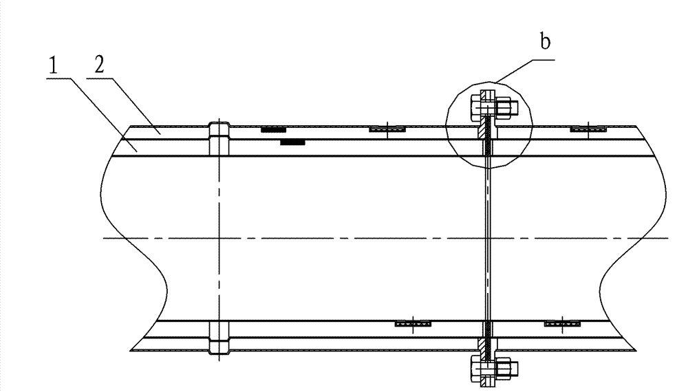
[0023] Embodiment 2: This embodiment is basically the same as Embodiment 1, except that the connecting piece is composed of a flange 6 , a seal 4 and a connecting bolt 7 . Sealed plugs 5 are welded to the ends of the inner and outer vacuum heat insulation pipes in the vacuum transmission pipe, and the plugs 5 are sealed and welded to the end faces of the inner and outer pipes of each layer of vacuum heat insulation pipes. The flange 6 is integrated with the plug 5 at the end of the outer vacuum heat insulation pipe 2, the outer end surface of the plug 5 at the end of the inner vacuum heat insulation pipe 1 is a plane, and the end surface of the flange is insulated from the inner vacuum heat insulation The outer end faces of the plug 5 at the end of the pipe 1 are on the same plane. Two adjacent vacuum transmission pipes are connected by flanges 6 through connecting bolts 7, and the seal 4 used between the flanges and the two adjacent vacuum transmission pipes is a gasket.

[...


PUM


Abstract

The invention relates to a vacuum transmission pipe and a connecting structure thereof. The vacuum transmission pipe is a multi-layer vacuum heat insulation pipe composed of at least three layers of stainless steel pipelines; wherein a vacuumized inner layer heat insulation pipe is arranged between an inner layer pipeline and a middle layer pipeline, a vacuumized outer layer vacuum heat insulation pipe is arranged between an outer layer pipeline and the middle layer pipeline, a middle layer vacuum heat insulation pipe is arranged between middle layer pipelines, two adjacent vacuum transmission pipes are connected by a connecting piece along axial direction, and end face joint thereof is provided with a sealing element. The invention has the advantages of simple structure, good heat preservation effect, long vacuum life and maintenance convenience and is especially applicable to heat transmission in the fields of solar power generation, heating and chemical industry.

Description

technical field [0001] The invention relates to a high-temperature medium conveying pipe, in particular to a vacuum conveying pipe and a connection structure for conveying high-temperature steam, oil or molten salt, and is suitable for heat transmission in the field of solar power generation, heat generation and chemical industry. Background technique [0002] Heat transfer pipe is a pipe widely used in solar power generation, heating and chemical industry. Existing heat transfer pipes generally wrap one or more layers of insulation materials on the outer surface of ordinary pipes. In the field of solar power generation, heat transfer is required Pipes have a good thermal insulation effect, so it is necessary to wrap multiple layers of thermal insulation materials on the outer surface of ordinary pipes, resulting in relatively thick heat transfer pipes and unsatisfactory heat transfer effects. Contents of the invention [0003] The purpose of the present invention is to so...

Claims


Application Information

Patent Timeline
Patent Type & Authority Patents(China)
IPC IPC(8): F16L59/065F16L59/08F16L59/10F16L9/02F16L19/00F16L23/12F16L23/16
Inventor 白明军吴平张琰周生宣
Owner 湖北贵族真空科技股份有限公司
Why Eureka
Try Eureka