Top board of microwave plasma processing device, plasma processing device and plasma processing method
A microwave plasma and processing device technology, which is applied in semiconductor/solid-state device manufacturing, discharge tubes, electrical components, etc., can solve the problems of increased manufacturing cost and complex shape of the top plate, and achieve the effect of stable plasma mode
- Summary
- Abstract
- Description
- Claims
- Application Information
AI Technical Summary
Problems solved by technology
Method used
Image
Examples
Embodiment approach
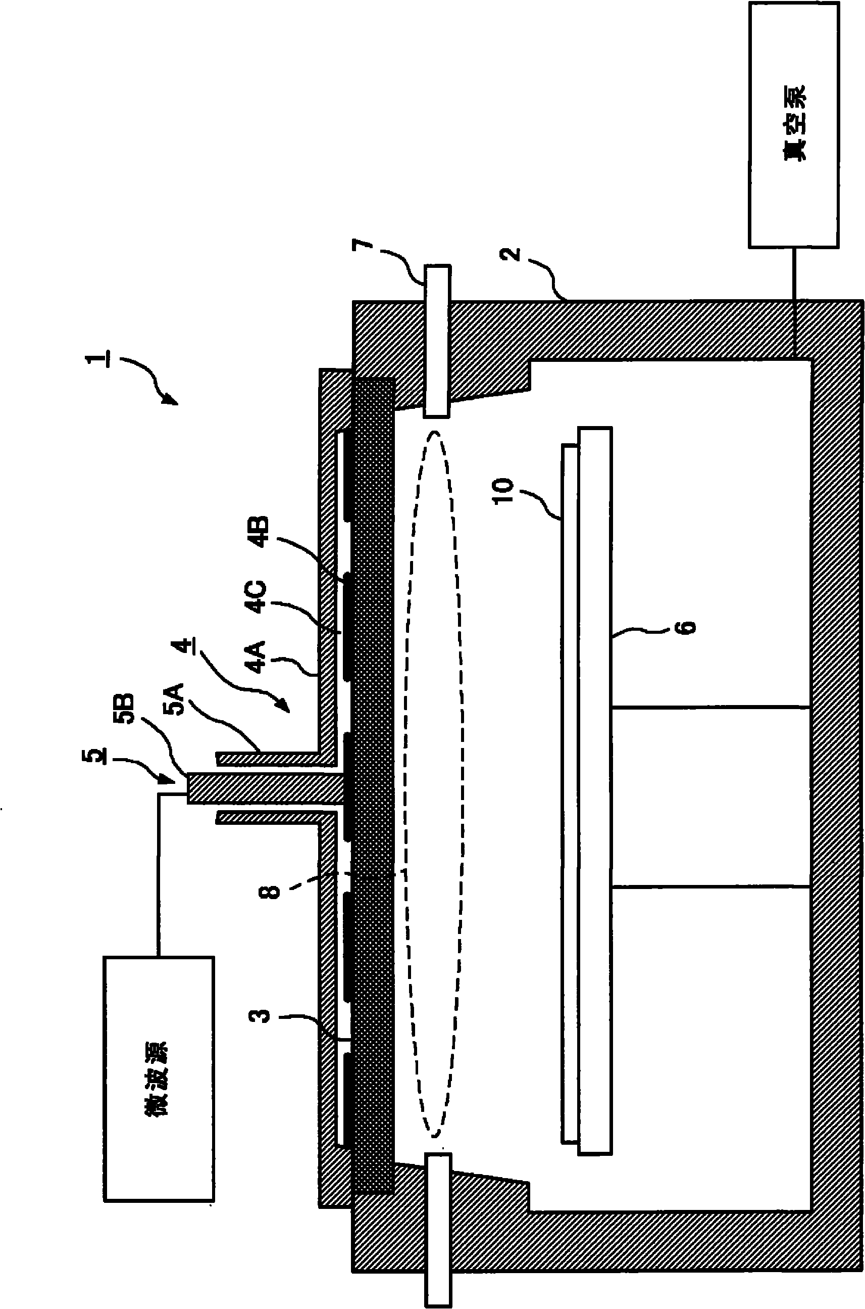
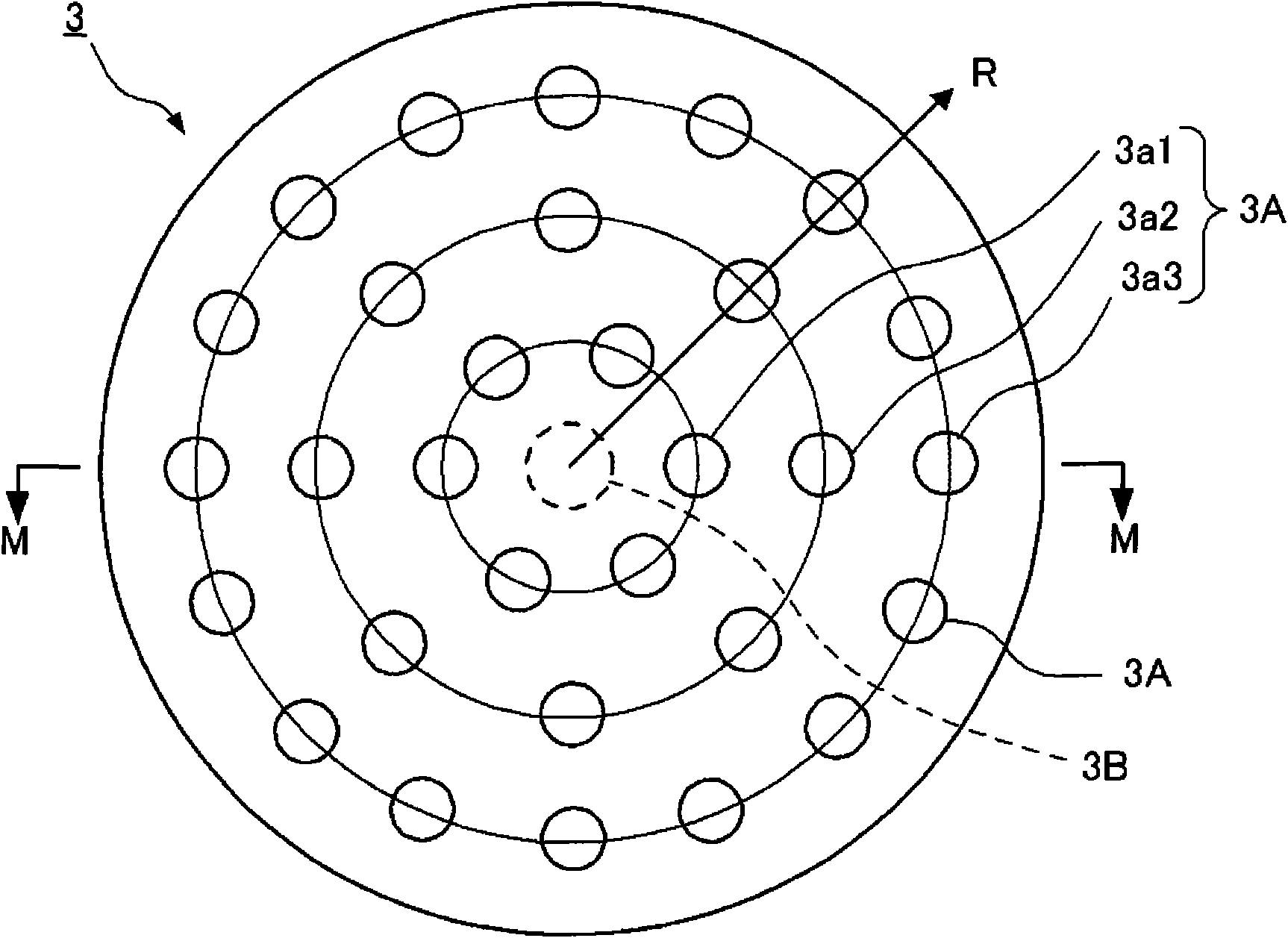
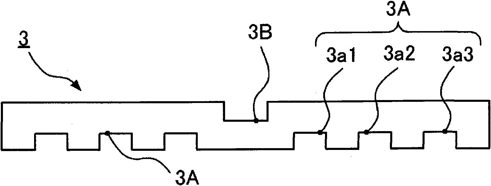
[0053] Hereinafter, the top plate of the microwave plasma processing apparatus according to the first aspect of the present invention will be described in detail with reference to the drawings. The same or equivalent parts in the figures are marked with the same reference numerals and the description is not repeated. figure 1 It is a cross-sectional view of a plasma processing apparatus according to an embodiment of the present invention. The plasma processing apparatus 1 includes a plasma generation chamber (chamber) 2, a top plate (dielectric) 3, an antenna 4, a waveguide 5, a substrate holding table 6 and a gas channel 7. The antenna 4 includes a wave guide (shielding member) 4A, a radial line slot antenna (RLSA) 4B, and a hysteresis plate (dielectric) 4C. The waveguide 5 is a coaxial waveguide having an outer waveguide 5A and an inner waveguide 5B.
[0054] The plasma generation chamber 2 of the plasma processing apparatus 1 is closed by a top plate 3. At this time, the ins...
no. 1 example
[0074] Figure 7A with Figure 7B This is an example in which a plasma experiment was performed on the top plate 3 according to the embodiment of the present invention, and the effect of the recess 3A of the top plate 3 was confirmed. Figure 7A This is an example (photograph) of plasma in the case of a flat top plate (hereinafter referred to as a conventional top plate), Figure 7B This is an example (photograph) of plasma in the case of the top plate having the recessed portion 3A of the present invention (hereinafter referred to as the top plate of the present invention).
[0075] The top plate 3 used in the experiment is formed of quartz, and the top plate of the present invention is a top plate having a plurality of recesses 3A on a conventional top plate. The conditions involved in plasma formation are universal, using argon gas and experimenting with a microwave power of 2000W and a pressure of 1.33Pa.
[0076] In the case of the conventional flat top plate, plasma generation...
no. 2 example
[0078] Figure 8A with Figure 8B This is an example (photograph) in which plasma is formed at different pressures using the top plate 3 according to the embodiment of the present invention. Figure 8A Shows the pressure 1.33Pa (condition A), Figure 8B The pressure is 66.65 Pa (condition B). The conditions other than the pressure are the same as in the first embodiment. The experiment was performed by setting the pressure of condition A to 1.33 Pa and the pressure of condition B to 66.65 Pa. Compare the presence or absence of plasma formation and the distribution of plasma when it is formed.
[0079] Such as Figure 8B It is shown that plasma can be generated in the same mode even when the pressure of the condition B is set to a higher state. In addition, in comparison Figure 8A versus Figure 8B In the case of, it can be seen that plasma is formed on the basis of having a plurality of recesses. If the plasma of condition A and condition B are compared, the size of the pl...
PUM
 Abstract
Description
Claims
Application Information
 - R&D
- Intellectual Property
- Life Sciences
- Materials
- Tech Scout
- Unparalleled Data Quality
- Higher Quality Content
- 60% Fewer Hallucinations
Browse by: Latest US Patents, China's latest patents, Technical Efficacy Thesaurus, Application Domain, Technology Topic, Popular Technical Reports.
© 2025 PatSnap. All rights reserved.Legal|Privacy policy|Modern Slavery Act Transparency Statement|Sitemap|About US| Contact US: help@patsnap.com


