Remote control energy saving lamp device and remote control method thereof

A technology for remote control and energy-saving lamps, which is applied in energy-saving lighting, lighting devices, and energy-saving ICT. The effect of strong interference ability

Inactive Publication Date: 2012-05-30
邓炳鸿 +1
View PDF0 Cites 0 Cited by
  • Summary
  • Abstract
  • Description
  • Claims
  • Application Information

AI Technical Summary

Problems solved by technology

[0003] Existing lighting control systems are mostly connected to each other by wire. The wiring, installation and maintenance are complicated, and the scalability is poor and lacks flexibility.
[0004] The existing lamps and lighting system controllers that use wireless communication to communicate with each other can solve the above problems to a certain extent, but generally seen in the market. The power switch with high-frequency carrier signal receiving function is used to replace the original wall switch. When the power switch with high-frequency carrier signal receiving function receives the high-frequency carrier signal emitted from the high-frequency remote control, it will output an appropriate wall switch Switch control signals to achieve the purpose of remote control, but the work of replacing wall switches and wiring is also more troublesome for ordinary users, and the remote control can only control the entire group of lamps, and cannot control individual bulbs or bulb combinations in the entire group of lamps. control, less flexible in application
[0005] Of course, there are some products that put the entire high-frequency carrier signal receiving circuit and demodulation control circuit into the energy-saving lamp, and then transmit the high-frequency control signal through the remote control to directly control the energy-saving lamp. It is convenient to use, and the user does not need to do any work to change the wall switch or wiring. However, due to the limited space inside the energy-saving lamp, it is difficult to configure a suitable high-frequency carrier signal receiving antenna and a simple and reliable receiving circuit. Therefore, this method is adopted. The practical remote control operation distance is generally short, about 5 to 15 meters. For those users who have a spacious home or remote control distance and want to control multiple light groups at the same time, the remote control distance cannot meet their daily use and future. Extended Functionality Requirements

Method used


Image

  • Remote control energy saving lamp device and remote control method thereof
  • Remote control energy saving lamp device and remote control method thereof
  • Remote control energy saving lamp device and remote control method thereof

Examples


Embodiment Construction

[0054] The present invention will be described in detail below in conjunction with the accompanying drawings.

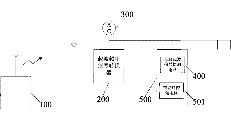
[0055] A remote control energy-saving lamp device, see attached figure 1 ,mainly includes:

[0056] A high-frequency remote control transmitter 100, used for transmitting a high-frequency carrier frequency with a remote control signal;

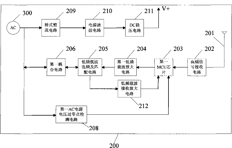
[0057] Carrier frequency signal converter 200, connected to AC power line network 300;

[0058] The low-frequency carrier signal detection circuit 400 is installed in the energy-saving lamp device 500. The input end of the low-frequency carrier signal detection circuit 400 is connected to the AC power line network 300, and the output end of the low-frequency carrier signal detection circuit 400 is connected to the energy-saving lamp control circuit 501.

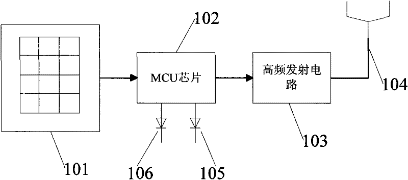
[0059] The circuit block diagram of high-frequency remote control transmitter 100 is referring to attached figure 2 , including a keyboard 101, a control chip 102, a high-freque...


PUM


Abstract

The invention provides a remote control energy saving lamp device. The device comprises at least one energy saving lamp device, a high frequency remote control emitter, a carrier frequency signal converter and a low frequency carrier signal detection circuit, wherein the carrier frequency signal converter is connected with an AC power line network and is used for demodulating remote control signals in high frequency carrier frequencies and modulating the remote control signals to a lower frequency carrier; the lower frequency carrier is transmitted by the AC power line network; and the low frequency carrier signal detection circuit is used for demodulating the remote control signals in the lower frequency carrier, and the output end of the low frequency carrier signal detection circuit isconnected with the control circuit of the energy saving lamp. The invention also provides a remote control method for the energy saving lamp device. The device and the method can perform remote control of the on / off of the lamp, dimming, delay of the on / off of the lamp, control of scenes and the like on the energy saving lamp in a wireless communication way under the condition of not changing wall supports or wiring operation. The device has the advantages of far remote control distance, convenient use, stable remote control signal receiving, strong anti-jamming capability, contribution to later functional expansion and the like.

Description

technical field [0001] The invention relates to the field of energy-saving lamps, in particular to a remote-control energy-saving lamp device and a remote control method thereof. Background technique [0002] The major trend in today's world is to promote environmental protection and reduce carbon dioxide emissions. This is also an inevitable direction for the country's sustainable development. Therefore, the sense of urgency for energy conservation has led many companies to devote themselves to the research of energy-saving light sources such as fluorescent lamps and LED lamps. with production. With the continuous advancement of technology, continuous improvement of performance, and the trend of gradually reducing costs, it must replace cheap but energy-intensive incandescent lamps as one of the main lighting sources. With the advancement of technology and the improvement of living standards, people There are various requirements for the lighting system, such as the abilit...

Claims


Application Information

Patent Timeline
Patent Type & Authority Patents(China)
IPC IPC(8): F21S2/00H05B41/38F21V23/00G08C17/02
CPCY02B20/202Y02B60/50Y02B20/00
Inventor 邓炳鸿司徒锦光
Owner 邓炳鸿
Why Eureka
Try Eureka