
Sealing loop forming pump

A technology of closed circuit and cylinder seat, which is applied in the direction of pumps, multi-cylinder pumps, liquid displacement machinery, etc., can solve the problems of noise vibration, cavitation, and enlargement, and achieve the effect of reducing pump noise and vibration

Inactive Publication Date: 2011-01-19
KANZAKI KOKYUKOKI MFG
View PDF8 Cites 9 Cited by
  • Summary
  • Abstract
  • Description
  • Claims
  • Application Information

AI Technical Summary

Problems solved by technology

However, as the cylinder block rotates, if high-pressure hydraulic fluid flows rapidly from the port on the discharge side into the hydraulic cylinder on the discharge side, cavitation occurs around the port, causing increased pump noise and vibration.
Above-mentioned Japanese Laid-Open Patent Application Laid-Open No. 2000-319942, Japanese Laid-Open Patent Application Laid-Open No. 10-169547, and Japanese Laid-Open Patent Application Laid-Open No. 2000-97146 do not show the above-mentioned disadvantages. means

Method used


Image

  • Sealing loop forming pump
  • Sealing loop forming pump
  • Sealing loop forming pump

Examples


Embodiment Construction

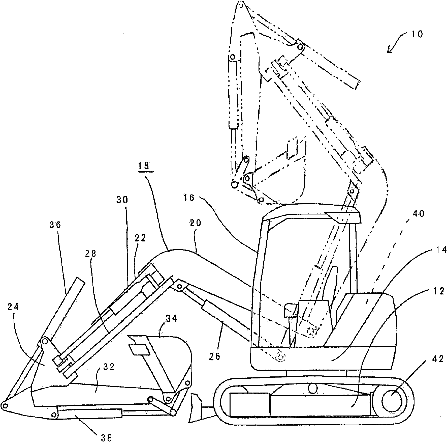
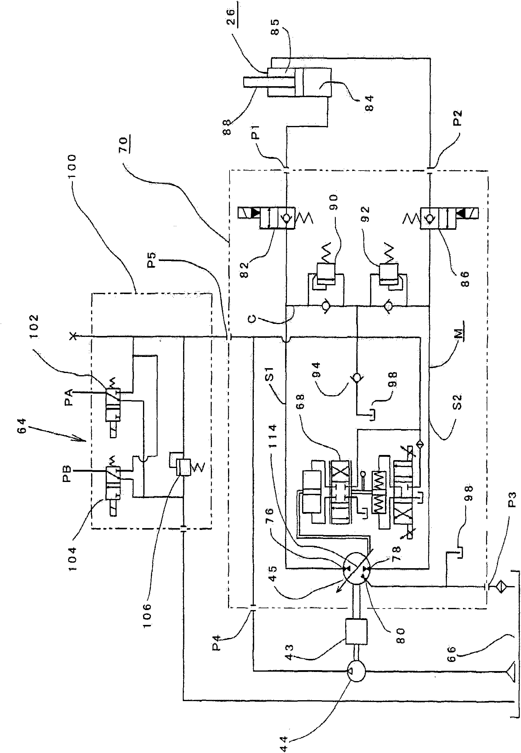
[0033] Embodiments of the present invention will be described in detail below with reference to the drawings. From Figure 1 to Figure 9 It is a figure which shows an example of embodiment of this invention. Such as figure 1 As shown, a backhoe 10, which is a vehicle having an elevating transmission device including a pump for constituting a closed circuit according to an embodiment of the present invention, is provided with a running device 12 including a pair of left and right crawlers, and a vehicle mounted on the running device 12 rotatably. The turntable 14 on the upper side and the cockpit 16 installed on the upper side of the turntable 14 . The cockpit 16 includes operating units such as a driver's seat and an operating lever. An excavation machine 18 is attached to the upper portion of the turntable 14 and in front of the cab 16 . The excavator 18 includes a first boom 20 , a second boom 22 and a third boom 24 . The base of the first cantilever 20 is installed on ...


PUM


Abstract

The invention relates to a sealing loop forming pump. A multi-port component (70) comprises a cylinder seat which is rotatingly disposed a housing (108) and consists of a plurality of cylinder seats of hydraulic cylinders (122) and a plurality of ports which is fixedly disposed on the valve plate (116) of the housing (108). A part of the ports are connected to the pressure chamber of the cantilever hydraulic cylinder, and the left are connected to an oil tank. A V-shaped groove which turns smaller forward is disposed at the end of each port opening which is at the same side of the rotation direction of the cylinder seat (112). The v-shaped grooves which are respectively disposed at the piston upper dead center and at the piston lower dead center are made bigger, while the v-shaped grooves which are disposed between the piston upper dead center and the piston lower dead center are made smaller.

Description

technical field [0001] The present invention relates to a pump for forming a closed circuit for selectively supplying and discharging operating oil to a pair of pressure chambers on both sides of a piston of a hydraulic transmission device. A closed circuit including a hydraulic transmission for a vehicle with a lifting transmission such as a ground working machine or an aerial ladder vehicle. Background technique [0002] In the past, excavators such as backhoes and other ground working machines installed excavators such as buckets or forks on the car body through cantilever or boom, etc., and the excavators were moved through hydraulic transmission devices such as hydraulic cylinders. for excavation work. For example, Japanese Patent Application Laid-Open No. 2000-319942 describes a backhoe as an excavator including a hydraulic operating device. [0003] In the case of the backhoe disclosed in Japanese Patent Application Laid-Open No. 2000-319942, a boom hydraulic cylind...

Claims


Application Information

Patent Timeline
IPC IPC(8): F04B1/22
Inventor 坂田浩二小和田七洋
Owner KANZAKI KOKYUKOKI MFG
Learn More