
Ground well lifting mechanism

A lifting mechanism and ground well technology, which is applied to aircraft parts, ground equipment, transportation and packaging, etc., can solve the problems of no emergency device, increase the installation area requirement, and high manufacturing cost, so as to save installation space, improve safety, and ensure safe effect

Inactive Publication Date: 2011-01-19
于亚鹏
View PDF0 Cites 4 Cited by
  • Summary
  • Abstract
  • Description
  • Claims
  • Application Information

AI Technical Summary

Problems solved by technology

[0002] The existing technology of the well lifting mechanism is to drive the clutch mechanism and gear transmission to carry out the lifting operation through the deceleration of the whole reducer, and its manufacturing cost is relatively high
It assembles the components on a fixed plate separately, and the space layout is scattered, which makes it necessary to increase the installation area requirements
In addition, there is no emergency device in the existing organization, and it is impossible to take effective protection measures for personnel, equipment and facilities, and the safety performance is poor.

Method used


Image

  • Ground well lifting mechanism
  • Ground well lifting mechanism
  • Ground well lifting mechanism

Examples


Embodiment Construction

[0009] The present invention will be further described in detail below in conjunction with the accompanying drawings and specific embodiments.

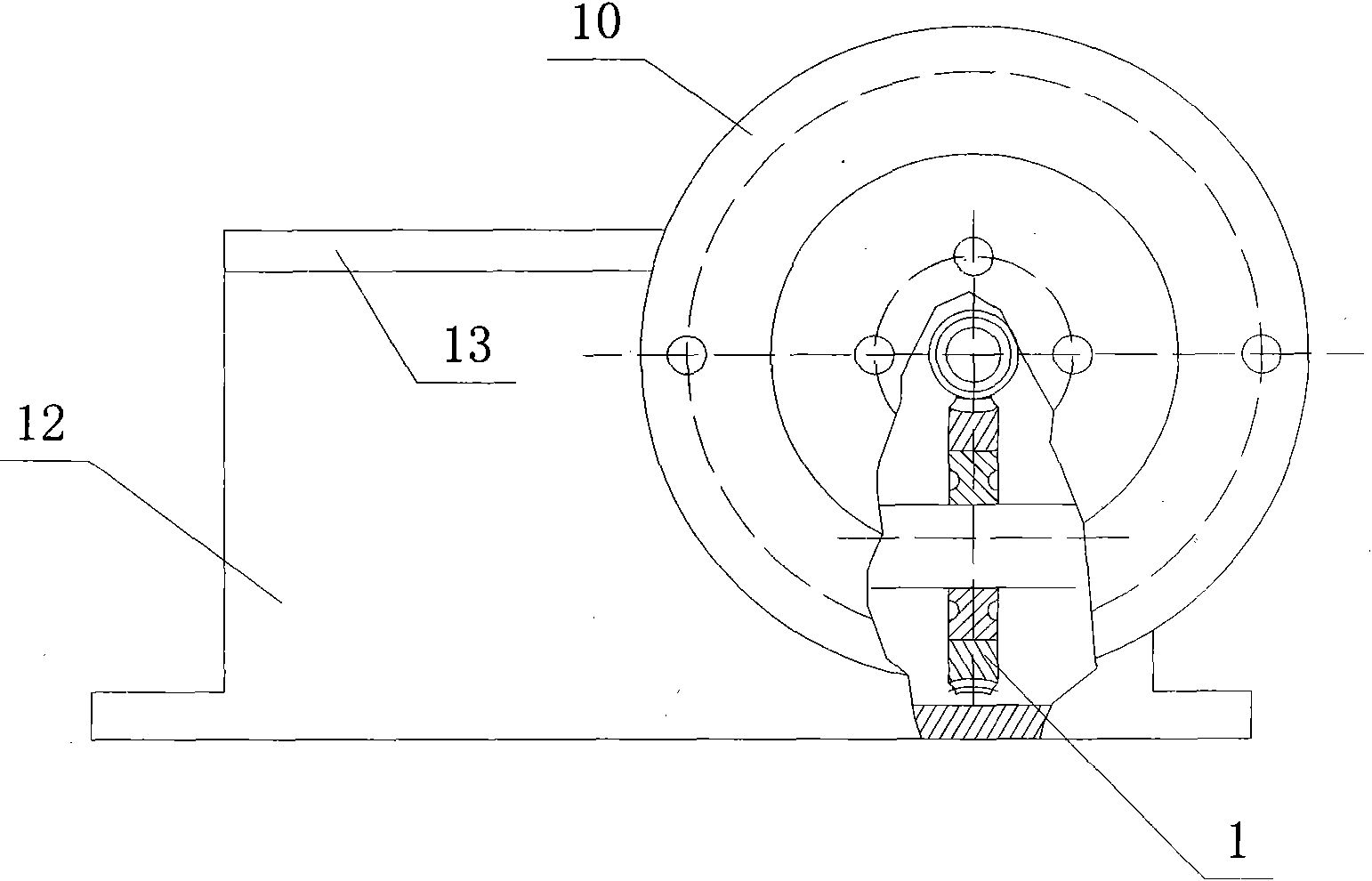
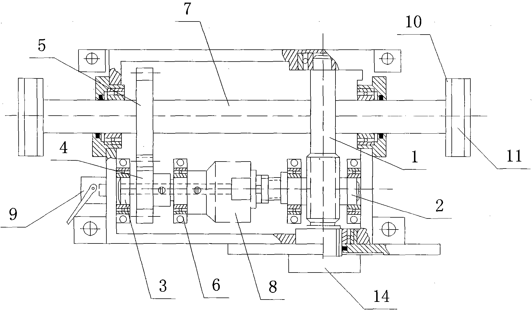
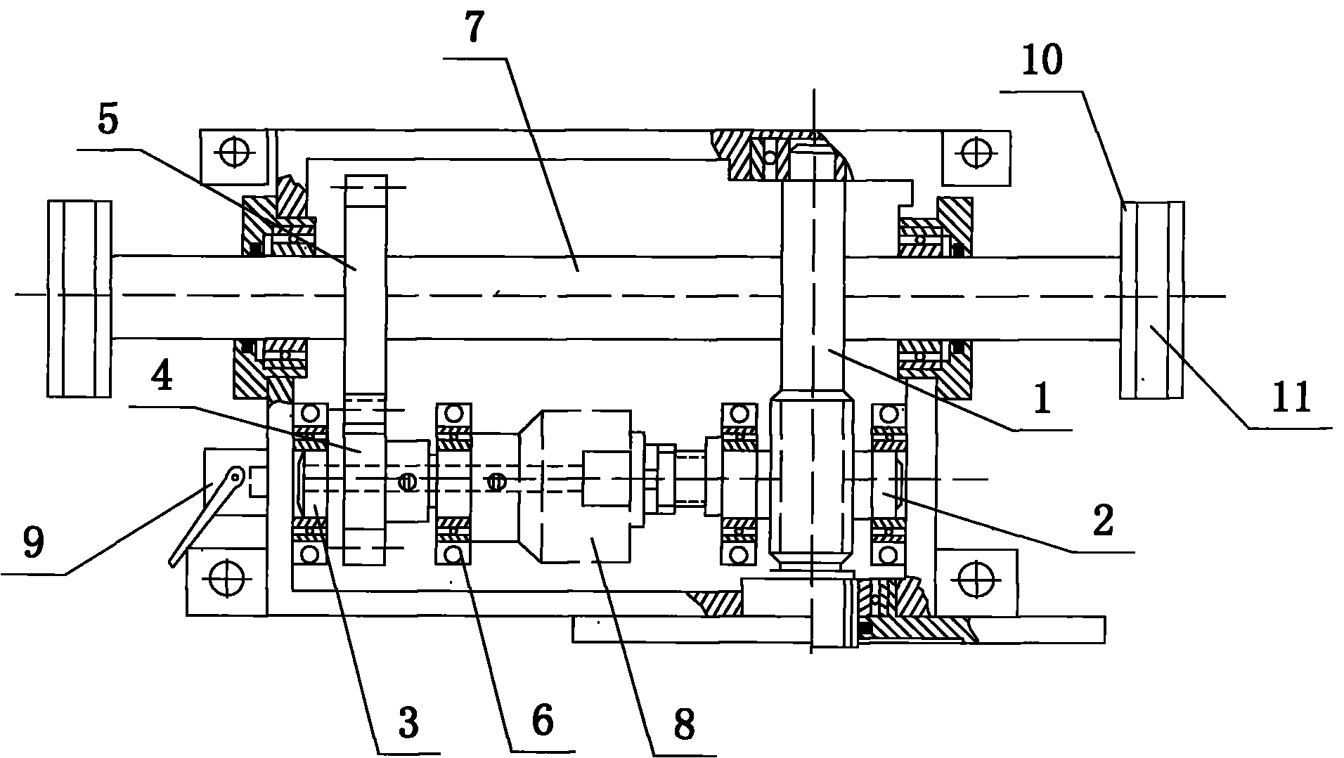
[0010] Such as figure 1 and figure 2 As shown, a ground well lifting mechanism includes a wheel 10 provided with a wheel groove 11, a box body 12 with a cover plate 13, and a worm gear mechanism 1, a worm gear shaft 2, a gear shaft 3, and a drive shaft 12 are installed in the box body 12. Gear 4, large gear 5, bearing card 6, lifting wheel shaft 7 and clutch 8; worm gear mechanism 1 is connected with clutch 8 through worm gear shaft 2, clutch 8 is connected with gear shaft 3 through bearing card 6, and gear shaft 3 is installed Drive gear 4, bull gear 5 are meshed with drive gear 4, lifting wheel shaft 7 is installed on the big gear 5, and wheel disc 10 is installed on the lifting wheel shaft 7 and places outside casing 12, and outside casing 12 also sets An Archimedes cam 9 cooperates with the gear shaft 3, and the motor 14 is con...


PUM


Abstract

The invention discloses a ground well lifting mechanism, which comprises a wheel disc with a wheel disc groove, a box body with a cover plate and a worm and gear mechanism, a worm shaft, a gear shaft, a driving gear, a gear wheel, a bearing clip, a lifting wheel disc shaft and a clutch which are arranged in the box body, wherein the worm and gear mechanism is connected with the clutch through the worm shaft; the clutch is connected with the gear shaft through the bearing clip; the driving gear is arranged on the gear shaft; the gear wheel is meshed with the driving gear; the lifting wheel disc shaft is arranged on the gear wheel; the wheel disc is arranged on the lifting wheel disc shaft and positioned outside the box body; an Archimedes cam is also arranged outside the box body to be meshed with the gear shaft; and a motor is connected with the worm and gear mechanism. In the invention, the component members of the lifting mechanism are combined in the box body according to functions, the members are used effectively, the cost is reduced, the installation area is small, quick falling and limiting functions are realized, the safety of the mechanism is improved, and the safety of relates person and materials are ensured.

Description

technical field [0001] The invention relates to a well lifting mechanism. Background technique [0002] The well lifting mechanism of the prior art is to drive the clutch mechanism and gear transmission to carry out the lifting operation through the deceleration of the whole speed reducer, and its manufacturing cost is relatively high. It is to assemble the components on a fixed plate respectively, and the space layout appears to be scattered, which makes it necessary to increase the installation area requirement. In addition, the existing institutions have no emergency devices, and cannot take effective protection measures for personnel, equipment and facilities, and the safety performance is poor. Contents of the invention [0003] Aiming at the shortcomings of the above-mentioned prior art, the present invention provides a well lifting mechanism, which can completely solve the above-mentioned problems. [0004] The technical scheme adopted by the present invention is:...

Claims


Application Information

Patent Timeline
Patent Type & Authority Applications(China)
IPC IPC(8): B64F1/36
Inventor 于亚鹏
Owner 于亚鹏
Learn More