Rotor of high-power permanent magnet motor and permanent magnet synchronous wind-driven generator using same

A permanent magnet motor, high-power technology, used in synchronous machines, wind power generation, synchronous machine parts and other directions, can solve problems such as deformation, magnetic flux leakage, etc., to reduce harmonic content, improve utilization, and prevent irreversible demagnetization. Effect

Active Publication Date: 2011-01-12
东元总合科技(杭州)有限公司
View PDF5 Cites 9 Cited by
  • Summary
  • Abstract
  • Description
  • Claims
  • Application Information

AI Technical Summary

Problems solved by technology

[0006] The purpose of the present invention is to solve the problem that the existing rotor adopts the permanent magnet embedded type high-power permanent magnet synchronous wind power generator in operation, the problem that the magnetic flux leakage between the adjacent two poles of the rotor is easy to occur and the magnetic path is easy to be squeezed and deformed. Provided are a high-power permanent-magnet motor rotor especially suitable for high-power permanent-magnet synchronous wind-driven generators, and a permanent-magnet synchronous wind-driven generator using the rotor

Method used


Image

  • Rotor of high-power permanent magnet motor and permanent magnet synchronous wind-driven generator using same
  • Rotor of high-power permanent magnet motor and permanent magnet synchronous wind-driven generator using same
  • Rotor of high-power permanent magnet motor and permanent magnet synchronous wind-driven generator using same

Examples


Embodiment approach

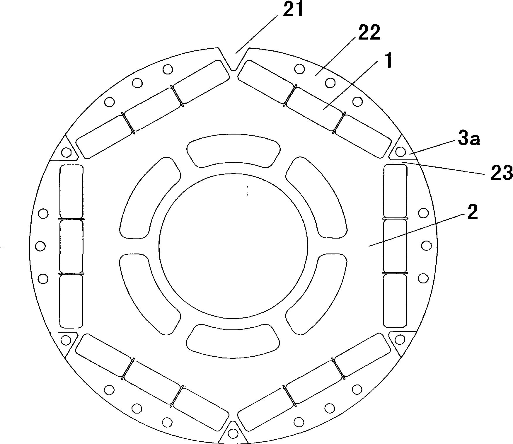
[0039] see figure 1 In the first embodiment of the permanent magnet motor rotor of the present invention, the rotor core 2 between the two adjacent poles embedded permanent magnets 1 is provided with a groove 21 along the rotor axis ( figure 1 It is a front view viewed from one end face of the rotor, so the groove is shown as a notch, and the shape of the notch is the cross-sectional shape of the groove), and the filler 3a with the same cross-sectional shape as the groove 21 is arranged in the groove 21.

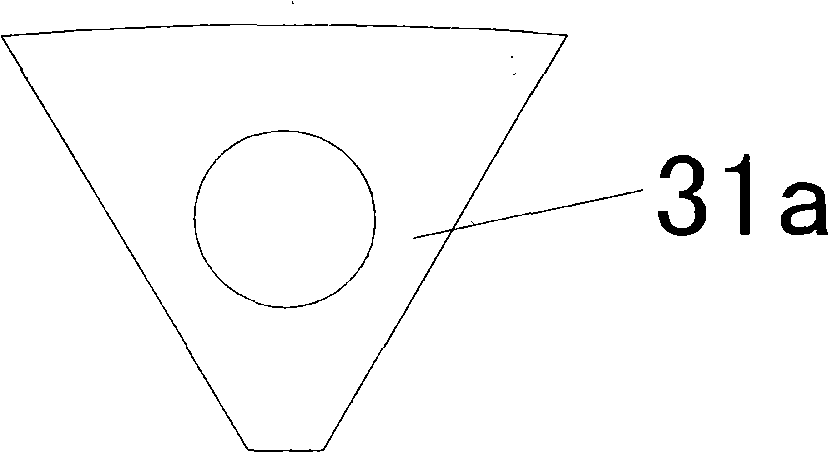
[0040] see figure 2 The filling body 3a is only composed of a magnetic isolation part 31a extending from the outer circumference of the rotor to the adjacent two-pole permanent magnet 1, and the entire filling body 3a is made of non-magnetic and non-conductive materials, so that it The magnetic separation part 31a between the permanent magnets 1 of two poles makes the magnetic field of the permanent magnets 1 between adjacent two poles not directly connected, which can avo...


PUM


Abstract

The invention provides a rotor of a high-power permanent magnet motor particularly suitable for a high-power permanent magnet synchronous wind-driven generator and the permanent magnet synchronous wind-driven generator using the rotor, wherein a permanent magnet embedded structure is adopted for the rotor; grooves are arranged on an iron core of the rotor between adjacent two pole permanent magnets along the axial direction of the rotor; and stuffing made of non-magnetic and non-conducting materials is arranged in the grooves and has the same cross section shape with that of the grooves. The invention can ensure that magnetic fields of the adjacent two pole permanent magnets can not be directly communicated because the stuffing is arranged between the adjacent two pole permanent magnets of the rotor, and thus, magnetic flux leakage can be avoided and the utilization rate of permanent magnet materials is enhanced; and the permanent magnets and pole pieces of the rotor are supported in the rotation course of the rotor because the stuffing is arranged between adjacent permanent magnets, and thus, a centrifugal force is prevented from acting on a magnetic flux path and the irreversible mechanical deformation of the magnetic flux path can not be caused because of excessive extrusion.

Description

technical field [0001] The invention relates to the technical field of motors, more specifically, to a high-power permanent magnet motor rotor and a permanent magnet synchronous wind generator using the rotor. Background technique [0002] Permanent magnet motors have the advantages of low loss and high efficiency, and are used more and more widely today when energy conservation and environmental protection are increasingly valued. For applications such as fans, pumps, compressors, etc. that operate at a continuous, constant speed and in one direction, ordinary asynchronous motors are gradually being replaced by permanent magnet motors due to the waste of electric energy caused by efficiency, power factor and other reasons. At the same time, the operating speed of many industrial machines needs to be set and adjusted arbitrarily, but the accuracy of speed control is not high. Due to the advantages of small size, high efficiency and energy saving, permanent magnet synchronous...

Claims


Application Information

Patent Timeline
Patent Type & Authority Applications(China)
IPC IPC(8): H02K1/27H02K21/02H02K1/28H02K21/00
CPCY02E10/725Y02E10/72
Inventor 刘立军冯雪晴
Owner 东元总合科技(杭州)有限公司
Why Eureka
Try Eureka