
Device for detecting stroke and speed of slide of forging and pressing equipment

A slider stroke and speed detection technology, which is applied in the direction of measuring devices, optical devices, and devices that measure the time required to move a certain distance, can solve the problem of low safety and reliability, large equipment vibration, and failure to meet the slider displacement speed. Requirements for detection accuracy and other issues to achieve the effect of improving safety and reliability

Inactive Publication Date: 2011-01-05
HUBEI FUSHENG FORGING MACHINE
View PDF8 Cites 8 Cited by
  • Summary
  • Abstract
  • Description
  • Claims
  • Application Information

AI Technical Summary

Problems solved by technology

[0002] The displacement speed of the slider movement of the forging equipment needs to be detected in time during automatic control, but the working environment of the forging equipment is relatively harsh, and the vibration of the equipment is large when the equipment is working. The displacement speed detection device of the slider movement of the forging equipment on the market is safe and reliable. Low, there is a large error in the detection of the displacement speed, which cannot meet the requirements for the detection accuracy of the slider displacement speed

Method used


Image

  • Device for detecting stroke and speed of slide of forging and pressing equipment
  • Device for detecting stroke and speed of slide of forging and pressing equipment
  • Device for detecting stroke and speed of slide of forging and pressing equipment

Examples


Embodiment Construction

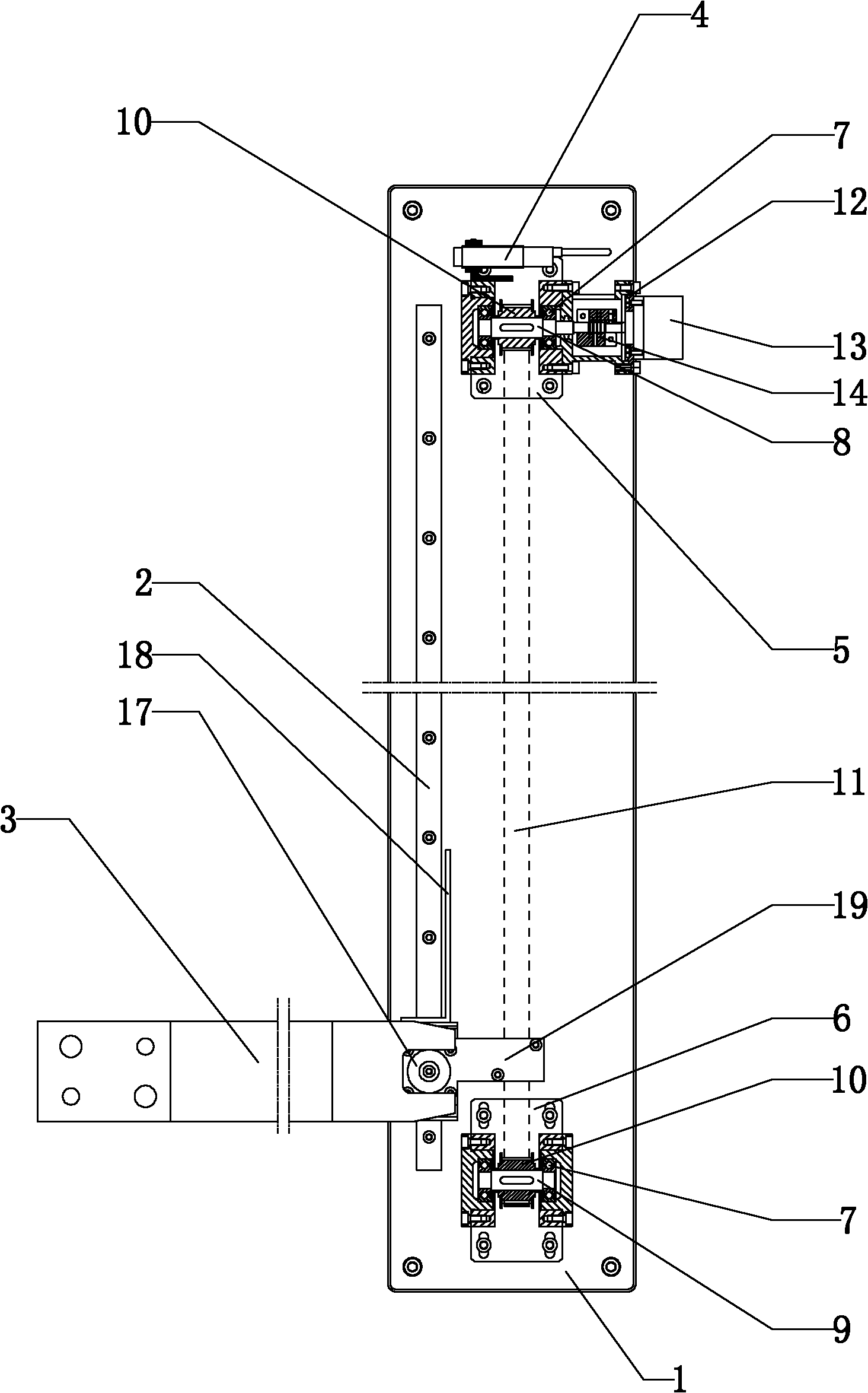
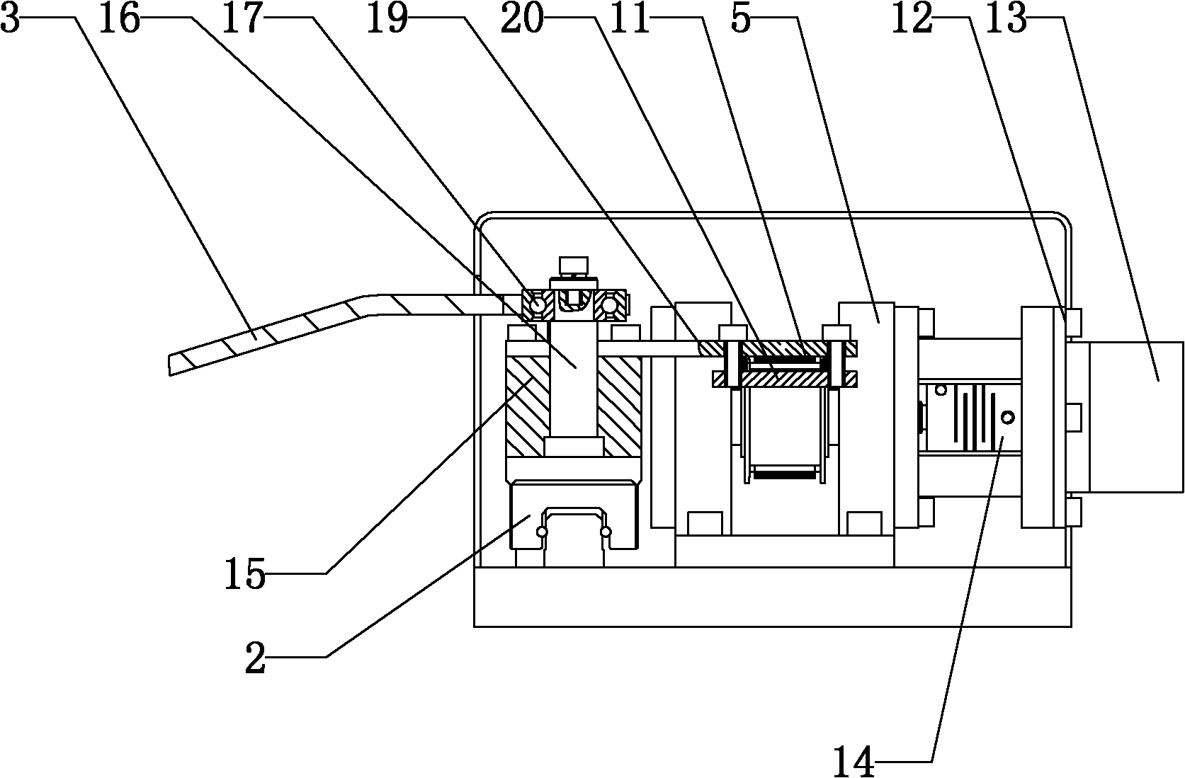
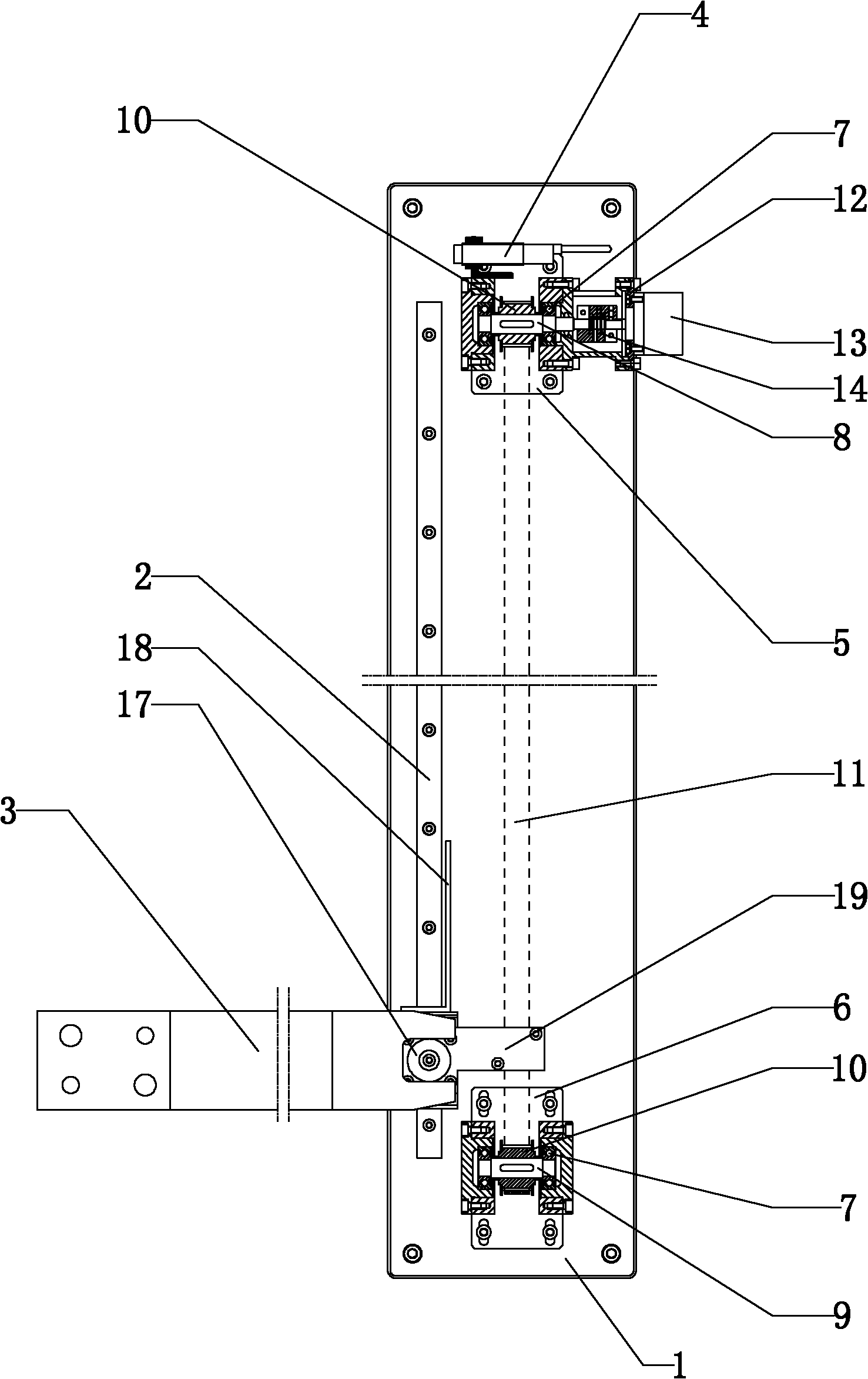
[0016] Such as Figure 1-2 As shown, a forging equipment slider stroke and speed detection device described in the embodiment of the present invention includes a base 1, a linear guide rail 2, a fixed dial 3 and a photoelectric switch 4, and the base 1 near the top and bottom An upper bearing seat 5 and a lower bearing seat 6 are provided respectively, and the inside of the upper bearing seat 5 and the lower bearing seat 6 are respectively fixed with the first shaft 8 and the second shaft 9 through the first bearing 7, and the first shaft 8 and the second shaft 9 The timing belt pulley 10 is fixed by a flat key on the top, and the timing belt 11 is connected between the two timing pulleys 10; the top of the upper bearing seat 5 is provided with a photoelectric switch 4, and the left and right positions of the photoelectric switch 4 are adjustable. The upper bearing seat 5 The right side of the encoder seat 12 is provided with an encoder seat 12, and the right side of the encod...


PUM


Abstract

The invention relates to a device for detecting the stroke and speed of a slide of forging and pressing equipment. The device comprises a base, a linear guide rail, a fixed poking plate and a photoelectric switch, wherein a part close to the top end and a part close to the bottom end on the base are provided with an upper bearing block and a lower bearing block respectively; a first shaft and a second shaft are fixed in the upper bearing block and the lower bearing block through a first bearing; synchronous belt pulleys are fixed on the first shaft and the second shaft through flat keys, and a synchronous belt is connected between the two synchronous belt pulleys; the right side of the upper bearing block is provided with a coder base, and a coder is fixed on the right side of the coder base; the left side of the synchronous belt is provided with the linear guide rail parallel with the synchronous belt; the linear guide rail is provided with a fixed base; the top part of the fixed base is provided with an upper pressure plate; and the right end of the upper pressure plate is fixed with the synchronous belt through a clamping plate. The device has the following advantages that: the photoelectric switch can send out a shutdown signal when the slide moves to the maximum stroke; the safe reliability is high; and the stroke and the speed of the slide of the forging and pressing equipment can be accurately detected according to the pulses sent out by the coder.

Description

technical field [0001] The invention relates to a device for detecting the stroke and speed of a sliding block of forging equipment. Background technique [0002] The displacement speed of the slider movement of the forging equipment needs to be detected in time during automatic control, but the working environment of the forging equipment is relatively harsh, and the vibration of the equipment is large when the equipment is working. The displacement speed detection device of the slider movement of the forging equipment on the market is safe and reliable. Low, there is a large error in the detection of the displacement speed, which cannot meet the requirements for the detection accuracy of the slider displacement speed. Contents of the invention [0003] The purpose of the present invention is to provide a forging equipment slider stroke and speed detection device, which has high safety and reliability and can accurately detect the stroke and speed of the forging equipment...

Claims


Application Information

Patent Timeline
IPC IPC(8): G01B11/02G01P3/68
Inventor 黄加林贺敬安熊幼斌
Owner HUBEI FUSHENG FORGING MACHINE
Learn More