
Quick automatic tensioning mechanism of dynamic triple connecting rod

A tensioning mechanism and link technology, applied in mechanical equipment, transmission devices, belts/chains/gears, etc., can solve the problems of slow screw, complex structure, high processing and manufacturing costs, and improve the ability to transmit loads and improve transmission. Efficiency, low manufacturing cost effect

Active Publication Date: 2013-08-07
GREENMAN MACHINERY
View PDF5 Cites 0 Cited by
  • Summary
  • Abstract
  • Description
  • Claims
  • Application Information

AI Technical Summary

Problems solved by technology

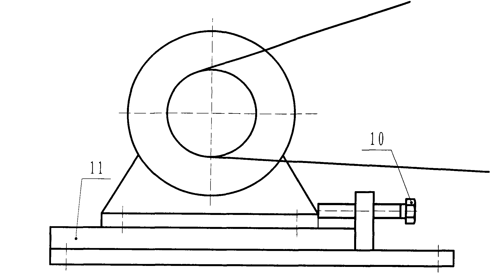
In this structure, 1. Tensioning the moving track is essential; and the manufacturing accuracy of the tensioning track and the parallelism of the installation are very high; 2. The adjustment of the screw during the tensioning process is a slow and repetitive process. 3. Because the belt will increase compared with the initial state during operation, this structure must be tensioned regularly
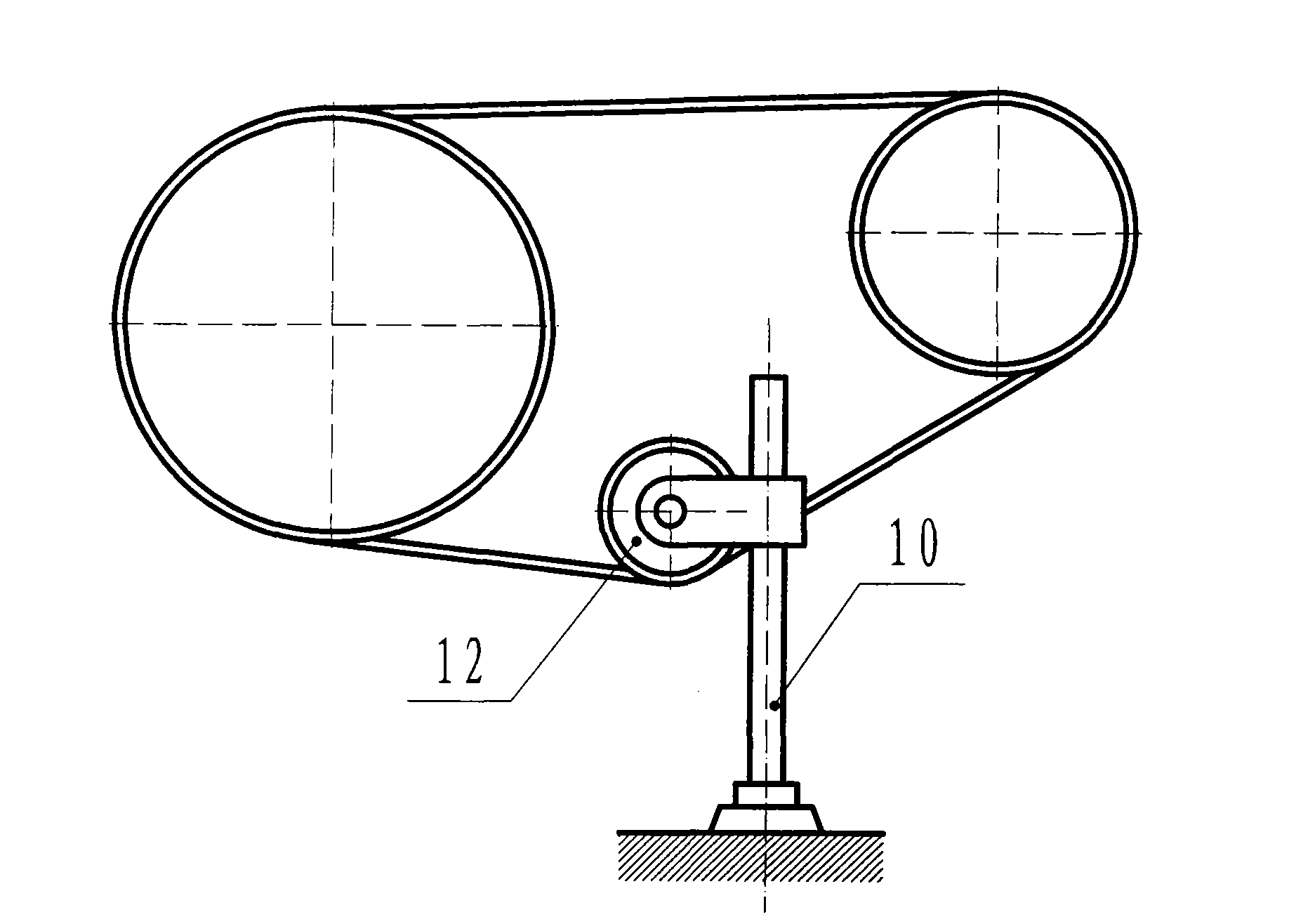
[0005] The second tensioning method: the tensioning wheel with the nut moves up and down by rotating the tensioning screw to play the role of tensioning the belt; similar to the first tensioning method, the adjustment of the screw during the tensioning process is a Slow and repetitive work, and the size of the tension force is not easy to control, this structure must also be tensioned regularly
[0006] These two tensioning methods must rotate the tensioning screw continuously to achieve the purpose of relaxation or tensioning when relaxing (leaving) or tensioning (closing). These two tensioning methods have complex structures and high manufacturing costs.

Method used


Image

  • Quick automatic tensioning mechanism of dynamic triple connecting rod
  • Quick automatic tensioning mechanism of dynamic triple connecting rod
  • Quick automatic tensioning mechanism of dynamic triple connecting rod

Examples


Embodiment Construction

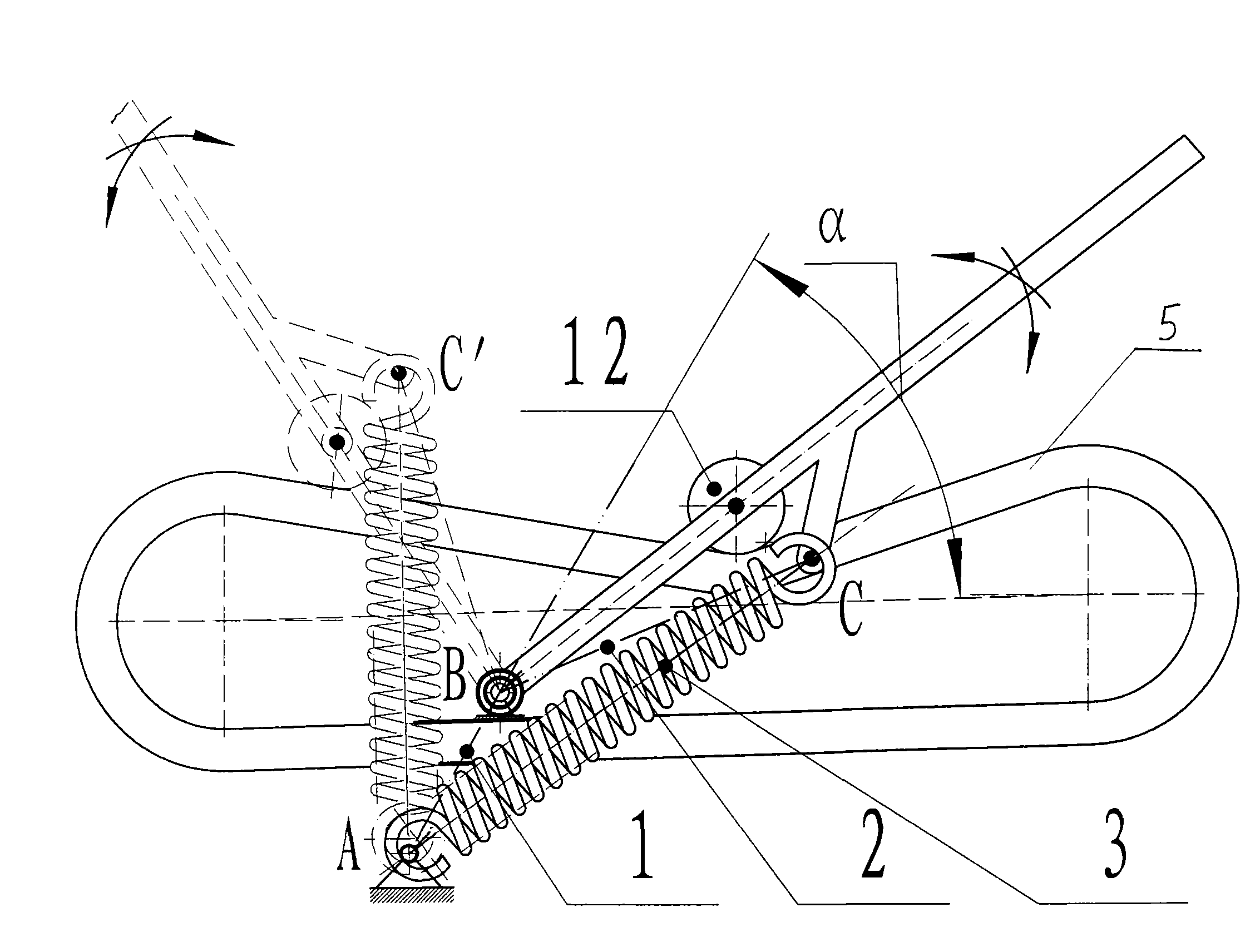
[0025] figure 1 , figure 2 , image 3 Among them, A is hinge I, and B is hinge II; hinge I and hinge II are respectively connected to different positions of frame 1, and hinge I and hinge II form connecting rod II, and its size and position are not fixed. Change; 2 is the connecting rod I, 3 is the connecting rod III, the lower end of the connecting rod I is connected to the hinge II, the middle part of the connecting rod I is connected with the cylindrical helical tension spring as the connecting rod III, and its connection point is C, and BC constitutes tension The connecting rod I and BC' in the (combined) state constitute the connecting rod I in the relaxed (off) state, the length and dimension of the connecting rod I remain unchanged, and the position can swing left and right through the movable hinge I; AC(C 1 、C 2 、C 3 ......C n ) constitutes the connecting rod III of the tensioned (combined) state, and AC' constitutes the connecting rod III of the relaxed (off) s...


PUM


Abstract

The invention discloses a quick automatic tensioning mechanism of a dynamic triple connecting rod, comprising a stand and a connecting rod III, wherein the stand is provided with a hinge I and a hinge II; the hinge I and the hinge II form a connecting rod II; the connecting rod III is a cylindrical spiral extension spring; the lower end of the cylindrical spiral extension spring is connected withthe hinge I; the hinge II is connected with the lower end of the connecting rod I; the middle of the hinge II is connected with the upper end of the cylindrical spiral extension spring; the middle ofthe connecting rod I is hinged with a pinch roller; and the hinge I, the hinge II and a connecting point of the middle of the connecting rod I and the cylindrical spiral extension spring form a triangular structure. The invention has the advantages of quickness, automatic tensioning without fixed period, simple mechanism, low manufacturing cost and convenient operation; and in addition, the invention can improve the capability of transmitting the load and the driving efficiency and prolong the service life of a bearing and an adhesive tape.

Description

technical field [0001] The invention relates to a tensioning mechanism, in particular to a dynamic three-link fast automatic tensioning mechanism Background technique [0002] In belt transmission, the preload of the belt has a great influence on its transmission capacity, life and shaft pressure. Insufficient pre-tightening force will reduce the ability to transmit loads, low efficiency, and cause the driving pulley to heat up sharply, and the belt will wear out; if the pre-tightening force is too large, the life of the belt will be reduced, the load on the shaft and bearing will increase, and the bearing will heat up. , wear and tear. Therefore, proper preload is an important factor to ensure the normal operation of the belt drive. [0003] There are two commonly used tensioning methods: first, adjust the distance between the shafts; second, use the tensioning wheel; please refer to the attached figure 1 , 2 , among the figure, 10 is the tensioning screw rod, and 11 is...

Claims


Application Information

Patent Timeline
Patent Type & Authority Patents(China)
IPC IPC(8): F16H7/08
Inventor 曾淑华蔡书径
Owner GREENMAN MACHINERY
Learn More