String drawing tension device for racket
A tensioning device and racket technology, applied to rackets, string rackets, sports accessories, etc., can solve problems such as increased movement costs, reduced elasticity, and loose network cables, and achieves convenient manufacturing and installation, prolong service life, and save costs. Effect
- Summary
- Abstract
- Description
- Claims
- Application Information
AI Technical Summary
Problems solved by technology
Method used
Image
Examples
Embodiment 1
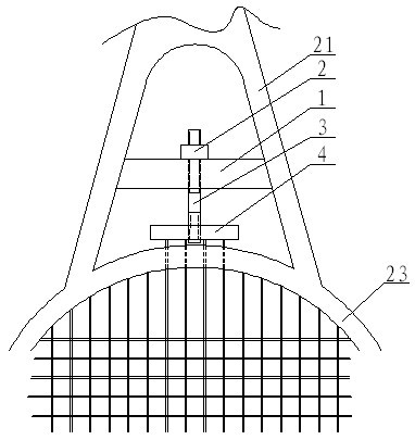
[0029] Example 1: as figure 1 As shown, a racket cable tensioning device includes a base 1 matched with a racket tripod 21, a force member 2, a force transmission member 3 and a connection member 4, and the force transmission member 3 passes through the base 1, one end of which is connected to the connecting piece 4, and the other end is provided with a reinforcing piece 2.
[0030] The present invention is used in this way: the present invention is arranged in the tripod 21 of the racket, the base 1 and the tripod 21 are arranged as a whole, and the network cable is extended and connected to the connecting piece 4. When the network cable needs to be tightened, Adjust the force part 2 by hand, the force part 2 transmits the force to the force transmission part 3, the force transmission part 3 then transmits the pulling force or rotation force to the connection part 4, and the connection part 4 pulls the network cable to achieve tension The purpose of the network cable. In th...
Embodiment 2
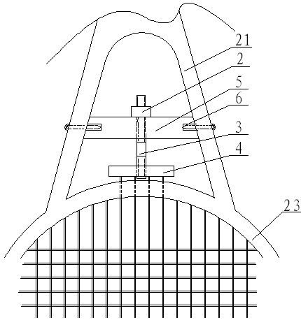
[0031] Example 2: as figure 2 As shown, the above-mentioned base is a trapezoidal plate 5 , and screw mounting holes 6 are provided on the end faces of both ends of the trapezoidal plate 5 . In the present invention, the base 1 can be an independent piece, and its connection with the racket's tripod 21 can be installed through the mounting holes of the bolts 1 .
Embodiment 3
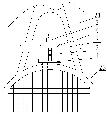
[0032] Example 3: as image 3 , 4 As shown, in this embodiment, the base includes a front mounting plate 7 and a rear mounting plate 8, the front mounting plate 7 and the rear mounting plate 8 are connected by bolts 9, and the front mounting plate 7 and the rear mounting plate 8 The bracket installation grooves 10, 10' are correspondingly arranged on the top.
[0033] The present invention is installed like this: first separate the front mounting plate 7 from the rear mounting plate 8, then place the racket triangle bracket 21 on the bracket mounting groove 10′ on the front mounting plate 7, and then place the rear mounting plate 8 on the The bracket mounting groove 10 corresponding to the bracket mounting groove 10 ′ of the front mounting plate is installed at the racket triangle bracket 21, and finally fixed by the bolt 9 to get final product.
PUM
 Abstract
Description
Claims
Application Information
 - R&D
- Intellectual Property
- Life Sciences
- Materials
- Tech Scout
- Unparalleled Data Quality
- Higher Quality Content
- 60% Fewer Hallucinations
Browse by: Latest US Patents, China's latest patents, Technical Efficacy Thesaurus, Application Domain, Technology Topic, Popular Technical Reports.
© 2025 PatSnap. All rights reserved.Legal|Privacy policy|Modern Slavery Act Transparency Statement|Sitemap|About US| Contact US: help@patsnap.com


