Quick-release device of a bicycle brake cable

a technology of brake cable and quick release, which is applied in the direction of bicycle brakes, cycle equipment, braking systems, etc., can solve the problems of taking a lot of time to change the wheel, and achieve the effect of quick release of the brake cable tension

Inactive Publication Date: 2011-08-30
TEKTRO TECH
View PDF12 Cites 1 Cited by
  • Summary
  • Abstract
  • Description
  • Claims
  • Application Information

AI Technical Summary

Benefits of technology

[0006]The main objective of the present invention is to provide a quick-release device of a bicycle brake cable, which is mounted relative to a brake lever for quickly releasing the tension of the brake cable.

Problems solved by technology

It will take a lot of time when changing the wheel.

Method used


Image

  • Quick-release device of a bicycle brake cable
  • Quick-release device of a bicycle brake cable
  • Quick-release device of a bicycle brake cable

Examples


Embodiment Construction

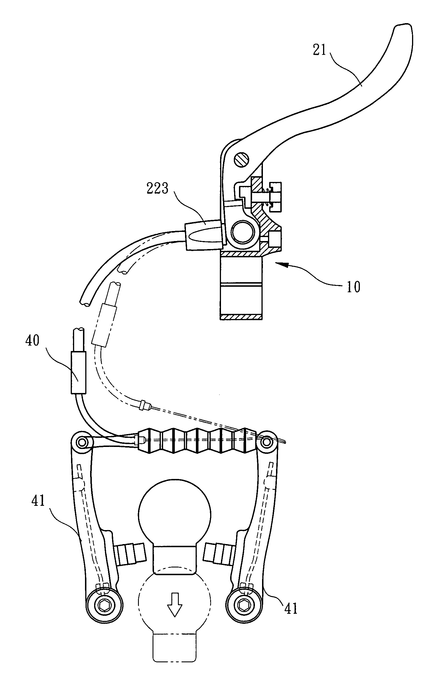
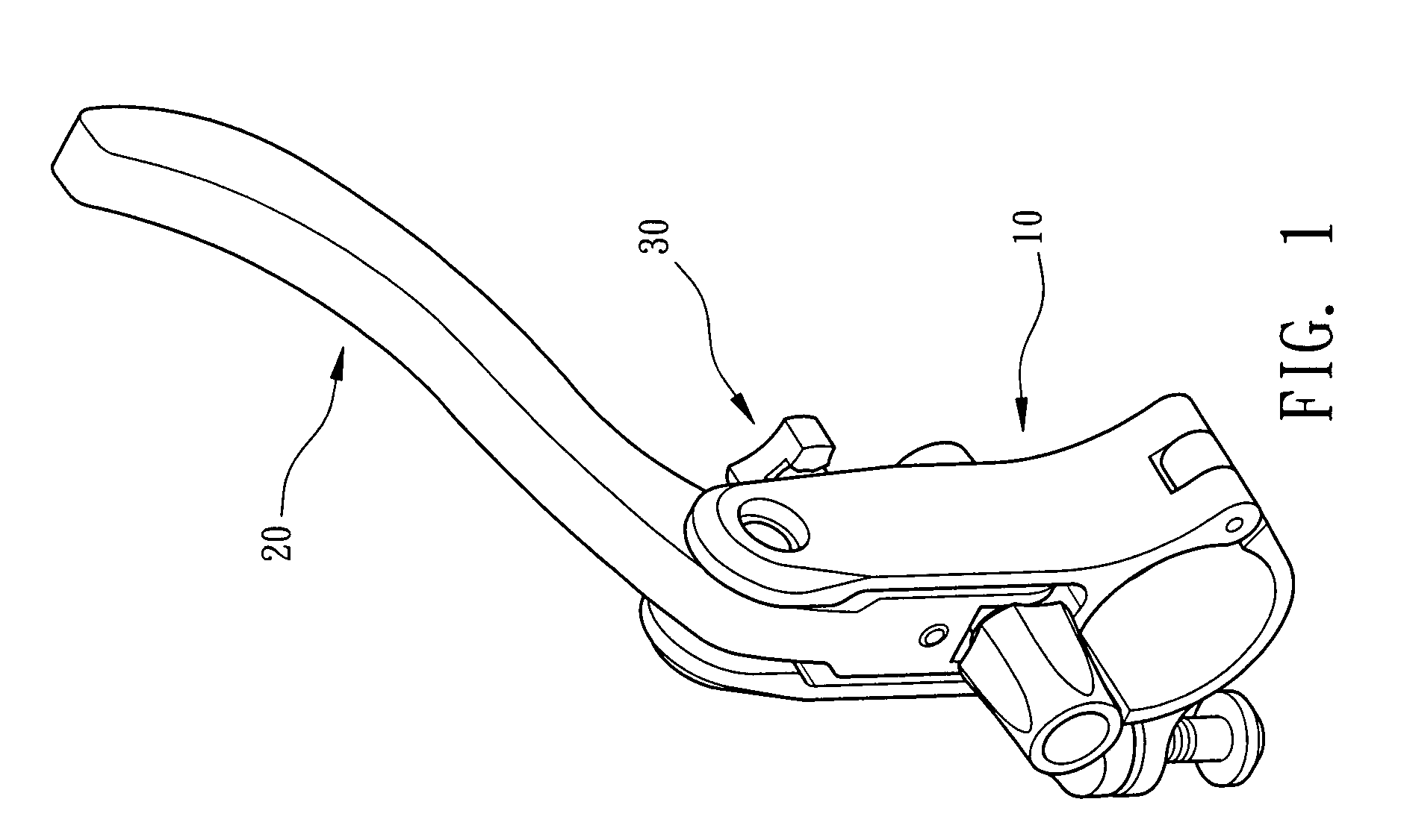
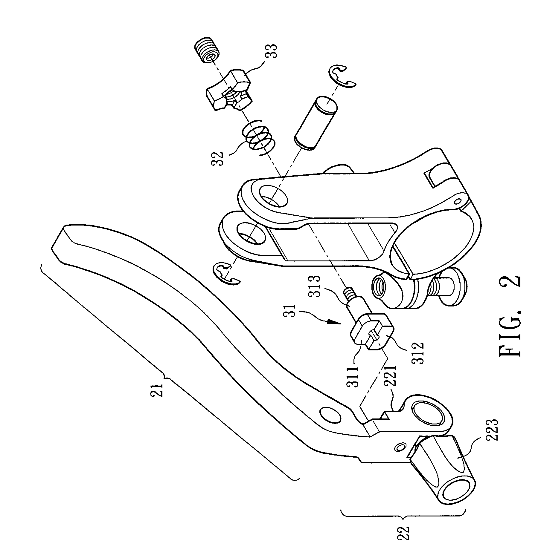
[0014]Referring to the drawings and initially to FIGS. 1-3, a quick-release device of a bicycle brake cable in accordance with the present invention comprises a main frame (10) adapted to be mounted to a handlebar of a bicycle, a lever (20) pivotally mounted to the main frame (10) and a push device (30) mounted in the main frame (10) to normally push the lever (20) for maintaining the tension of the brake cable.

[0015]The lever (20) is L-shaped and has a pivot point that divided the lever (20) into a holding section (21) and a drive section (22), wherein the drive section (22) is received in the main frame (10) when the lever (20) is in a free condition.

[0016]The drive section (22) of the lever (20) has a push face (221) formed on one side thereof and facing the main frame (10), and a groove (222) defined in the drive section (22) between the push face (221) and the pivot point of the lever (20). A pusher (223) is mounted to a free end of the drive section (22). The pusher (223) push...


PUM


Abstract

A quick-release device of a bicycle brake cable includes a main frame mounted to a handlebar of the bicycle, a lever pivotally mounted to the main frame and a push device mounted in the main frame to normally push the lever for selective changing the position between the lever and the push device and the tension of the brake cable.

Description

BACKGROUND OF THE INVENTION[0001]1. Field of the Invention[0002]The present invention relates to quick-release device, and more particularly to a quick-release device of a bicycle brake cable, which is mounted relative to a brake lever.[0003]2. Description of Related Art[0004]A brake device of a bicycle must be designed under two factors including brake effect and quickly releasing the tension of the brake cable when changing the wheel. A conventional brake device of a bicycle includes an L-shaped guider mounted to a free end of a brake arm and two brake pads for clamping the wheel rim to achieve the effect of brake. However, the two brake pads are very closed to the wheel rim and the tire has a diameter greater than a width of the wheel rim. Consequently, the tension of the brake cable must be greatly released to enlarge the width between the two brake pads before changing the wheel. As a result, the tension of the brake cable must be adjusted again after changing the wheel. It wil...

Claims


Application Information

Patent Timeline
Patent Type & Authority Patents(United States)
IPC IPC(8): B62L3/00
CPCB60T11/046B62L3/02F16C1/16F16C1/14Y10T74/20438Y10T74/20287F16C2326/20
Inventor TSAI, SZU-FANG
Owner TEKTRO TECH
Why Eureka
Try Eureka