Perforation processing method for printing substrate
A hole processing method and printed substrate technology, which are applied in the fields of printed circuit, metal processing, printed circuit manufacturing, etc., can solve the problems of deviation in plating thickness, reduced reliability of electrical connection, inability to facilitate hole processing, etc., and increase the number of processes , the effect of improving reliability
- Summary
- Abstract
- Description
- Claims
- Application Information
AI Technical Summary
Problems solved by technology
Method used
Image
Examples
Embodiment 1
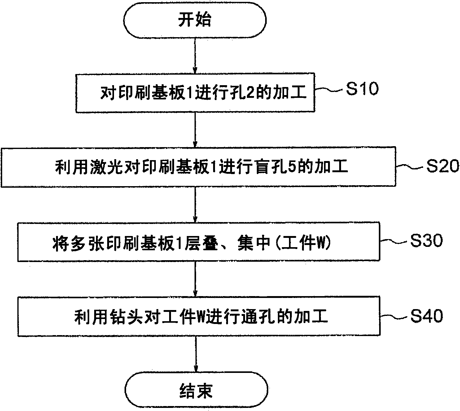
[0045] figure 1 It is a flow chart showing the overall processing procedure of the method of drilling the printed circuit board 1 according to the first embodiment of the present invention.
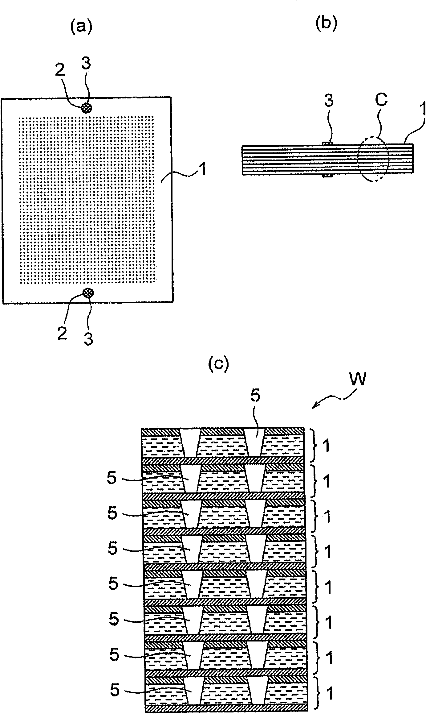
[0046] In this processing sequence, firstly, the laser pair using the laser processing machine and the Figure 7 (a)~ Figure 7 Before the printed circuit board 1 having the same printed circuit board structure as described in (c) is subjected to hole processing, a process of forming peripheral holes 2 for positioning and fixing by using a drill at a predetermined position on the peripheral portion of the printed circuit board 1 is performed. This is a step of processing the (peripheral) hole 2 on the printed circuit board 1 (step S10 ). In addition, this process is a preparatory process before carrying out the following 1st process.
[0047] Next, a first step of processing a hole from the conductor layer 1a to the surface of the conductor layer 1b at a predetermined position of the pr...
Deformed example 1
[0058] Figure 4 It is an enlarged cross-sectional view of a main part in the plate thickness direction showing a basic structure of a first modification example of a workpiece of a superimposed body that can be applied in the above-mentioned processing procedure.
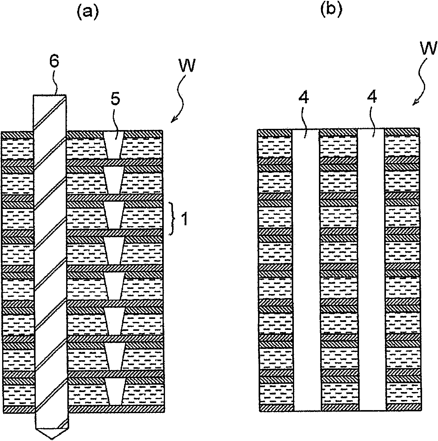
[0059] Such as Figure 4 As shown, the workpiece W1 of the superimposed body here is a printed substrate 1 that has been processed with a laser for blind holes 5 in the previous first process and a printed substrate 1 that has not been processed with blind holes 5 to carry out blind holes. 5. The processed printed circuit boards are arranged in the upper part and are sequentially stacked. Even if such a workpiece W1 is targeted, as in the case of the first embodiment, the drilling process of the through hole 4 can be performed using the drill 6 in the third step. At this time, since the processing time of the blind hole 5 in the first step can be reduced by half compared with the case where the blind hole 5 is pr...
Deformed example 2
[0061] Figure 5 It is an enlarged cross-sectional view of the main part in the plate thickness direction showing the basic structure of the second modified example of the superimposed workpiece W2 which can be applied in the above-mentioned processing procedure.
[0062] Such as Figure 5 As shown, the stacked workpiece W2 here has a laminated structure in which truncated conical through-holes 5 a are formed on each printed board 11 by laser instead of blind holes 5 formed on each printed board 1 in Example 1. That is, the through-holes 5a of the respective printed circuit boards 11 of the workpiece W2 are on the entrance side (in the Figure 5 In the example, the large diameter part) are concentrated on the upper side and the outlet side (in the Figure 5 In the example, the small diameter part) is concentrated on the lower side.
[0063] If the workpiece W2 with such a structure is used as an object, the efficiency of drilling the through hole 4 using the drill 6 in the ...
PUM
 Abstract
Description
Claims
Application Information
 - R&D Engineer
- R&D Manager
- IP Professional
- Industry Leading Data Capabilities
- Powerful AI technology
- Patent DNA Extraction
Browse by: Latest US Patents, China's latest patents, Technical Efficacy Thesaurus, Application Domain, Technology Topic, Popular Technical Reports.
© 2024 PatSnap. All rights reserved.Legal|Privacy policy|Modern Slavery Act Transparency Statement|Sitemap|About US| Contact US: help@patsnap.com


