
Blanking and drawing composite die for aluminium shell of capacitor

A capacitor and composite mold technology, applied in capacitors, capacitor manufacturing, circuits, etc., can solve problems affecting product quality and production efficiency, difficult to reduce production costs, waste and defective products, etc. The effect of cracking and reducing manufacturing cost

Active Publication Date: 2010-12-29
江苏奥星电子有限公司
View PDF3 Cites 6 Cited by
  • Summary
  • Abstract
  • Description
  • Claims
  • Application Information

AI Technical Summary

Problems solved by technology

[0003] The disadvantage of the above mold is: due to the large aspect ratio (the ratio of length to diameter) of the aluminum shell of the capacitor, the extension of the aluminum plate during the deep drawing process is relatively large, and it is easy to be pulled and cracked due to the unbalanced extension around the aluminum shell. situation, leading to the generation of waste and defective products; affecting product quality and production efficiency, and it is difficult to reduce production costs

Method used


Image

  • Blanking and drawing composite die for aluminium shell of capacitor
  • Blanking and drawing composite die for aluminium shell of capacitor
  • Blanking and drawing composite die for aluminium shell of capacitor

Examples


Embodiment Construction

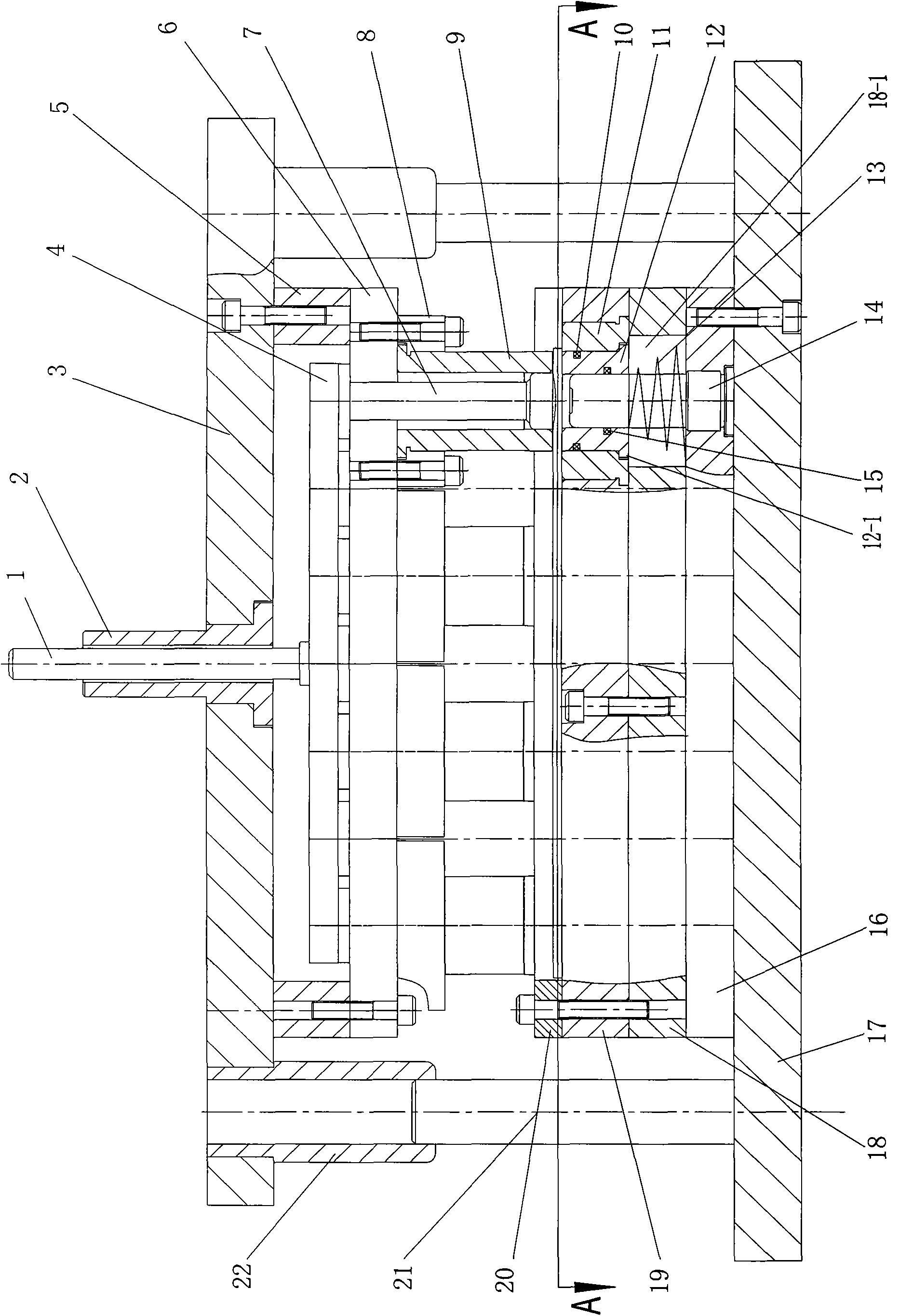
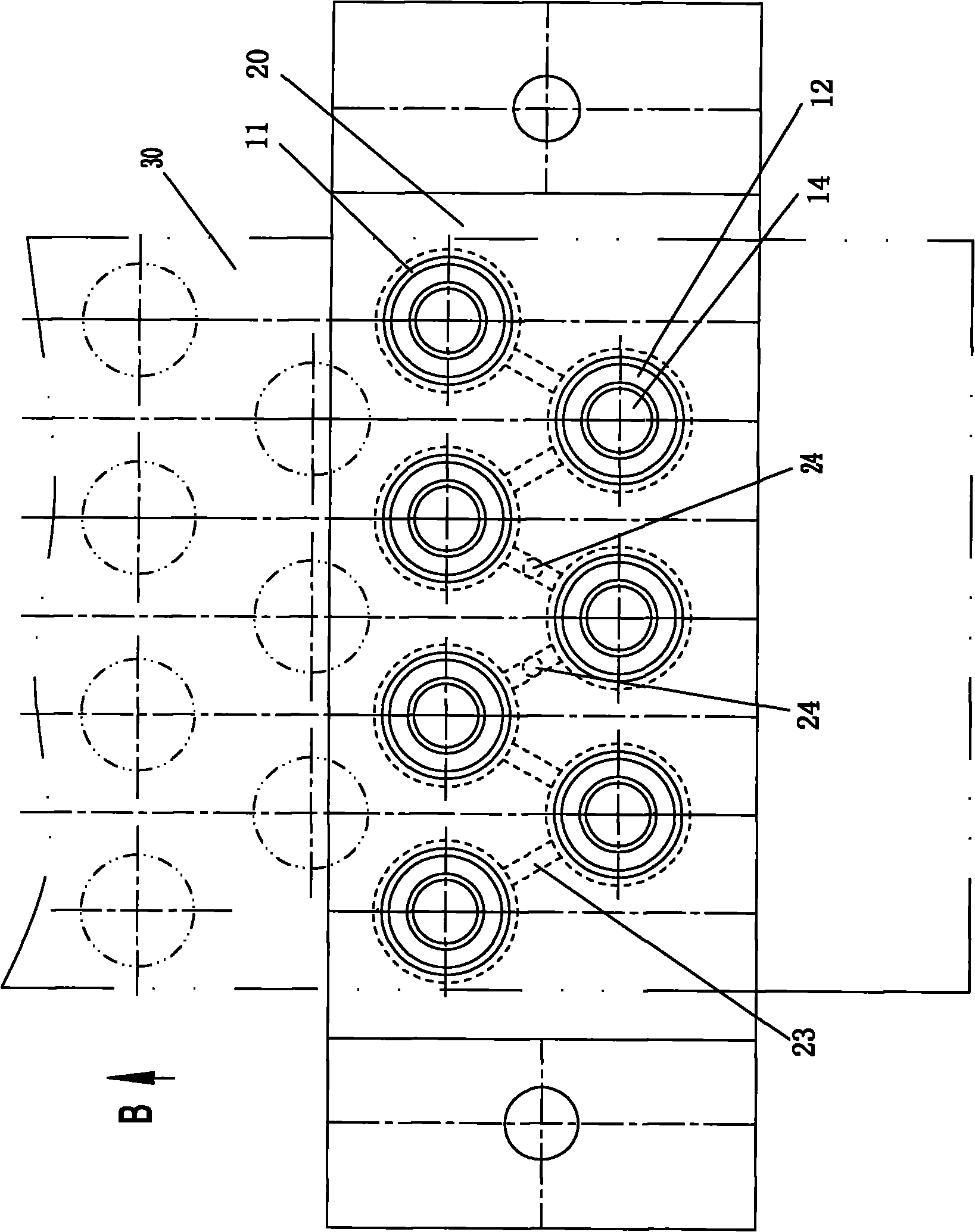
[0017] As shown in the accompanying drawings, the capacitor aluminum shell blanking and deep drawing composite mold includes a lower mold base 17 fixed on the frame and an upper mold base 3 driven by a power mechanism and relatively moving with the lower mold base through guide rails (Fig. The guide rail shown in is a guide post 21 vertically fixed on the lower die base, and a guide sleeve 22 which is vertically fixed on the upper die base and can be slidably matched with the guide post), and several concave holes are vertically fixed on the lower die base. Die 11, a punch 14 is vertically fixed in the center of the cavity of each die, and several concave-convex dies that are vertically suspended downwards and are respectively matched with the die and punch one by one are fixed on the upper die. 9 (it can be seen in the figure: the punch holder 16, the lower backing plate 18, the die holder 19 and the lower die cover 20 are fixed sequentially from bottom to top on the lower mol...


PUM


Abstract

The invention relates to a blanking and drawing composite die. The provided die has the characteristics of good product quality, high production efficiency and low cost. The invention adopts a technical scheme that: the blanking and drawing composite die for an aluminium shell of a capacitor comprises a lower die seat and an upper die seat, wherein a plurality of vertically arranged female dies are fixed on the lower die seat; a male die is vertically fixed in the centre of the cavity of each female die; and a plurality of female and male dies which are matched with the female dies and the male dies one by one are fixed on the upper die seat. The blanking and drawing composite die is characterized in that: a pressure ring capable of vertically sliding is sleeved on each male die respectively; an upward pressure is applied by a pressure spring onto the bottom end of the pressure ring; the outer circumferential surface of the pressure ring is matched with the female dies; and a convex edge for limiting the outer circumferential surface is arranged on the outer circumferential surface. A pneumatic tube network is also arranged in the lower die seat, wherein the pneumatic tube network is respectively communicated with the cavity of each female die so as to apply the upward air pressure onto the pressure ring; and air from an external air source is supplied to the pneumatic tube network through an externally connected air pipe.

Description

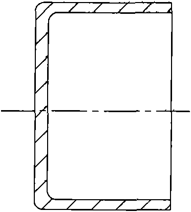
technical field [0001] The invention relates to a mechanical processing die, in particular to a blanking and deep drawing die for processing aluminum shells of capacitors. Background technique [0002] Capacitor aluminum shells are usually stamped by dies. In this mold, several concave and convex molds extending vertically downward are fixed on the concave and convex mold fixing plate of the upper mold base; the concave and convex mold fixing plate and the punch fixing plate are fixed on the lower mold base, and the number of A die that is equal to the concave-convex die and whose working position is suitable for the concave-convex die. A punch is vertically set in the center of each die. The bottom of the punch goes down through the die fixing plate and is fixed on the punch fixing plate. superior. When working, driven by the power mechanism, the upper mold base moves up and down through the guide column and guide sleeve structure set between the lower mold base, blanking...

Claims


Application Information

Patent Timeline
Patent Type & Authority Applications(China)
IPC IPC(8): H01G13/00B21D37/10B21D22/22
Inventor 詹有耕
Owner 江苏奥星电子有限公司
Learn More