Eureka AIR delivers breakthrough ideas for toughest innovation challenges, trusted by R&D personnel around the world.

Valve control type energy-saving dehumidifier

A dehumidifier, valve-controlled technology, used in refrigerators, compressors, heating methods, etc., can solve problems such as waste, and achieve the effect of reducing energy consumption

Inactive Publication Date: 2010-12-29
杭州松井电器有限公司
View PDF5 Cites 6 Cited by
  • Summary
  • Abstract
  • Description
  • Claims
  • Application Information

AI Technical Summary

Problems solved by technology

[0003] The above-mentioned dehumidification process must rely on a high-temperature and high-pressure condenser, a low-temperature and low-pressure evaporator, one generates high temperature, and the other produces low temperature. The two energy sources of cold and heat are also needed in our daily life and industrial and agricultural production. , if the two energy sources cannot be well regulated and utilized, it will be a great waste

Method used

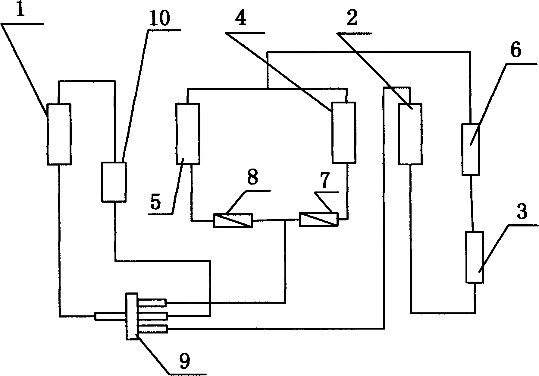

Image

  • Valve control type energy-saving dehumidifier
  • Valve control type energy-saving dehumidifier
  • Valve control type energy-saving dehumidifier

Examples


Embodiment 1

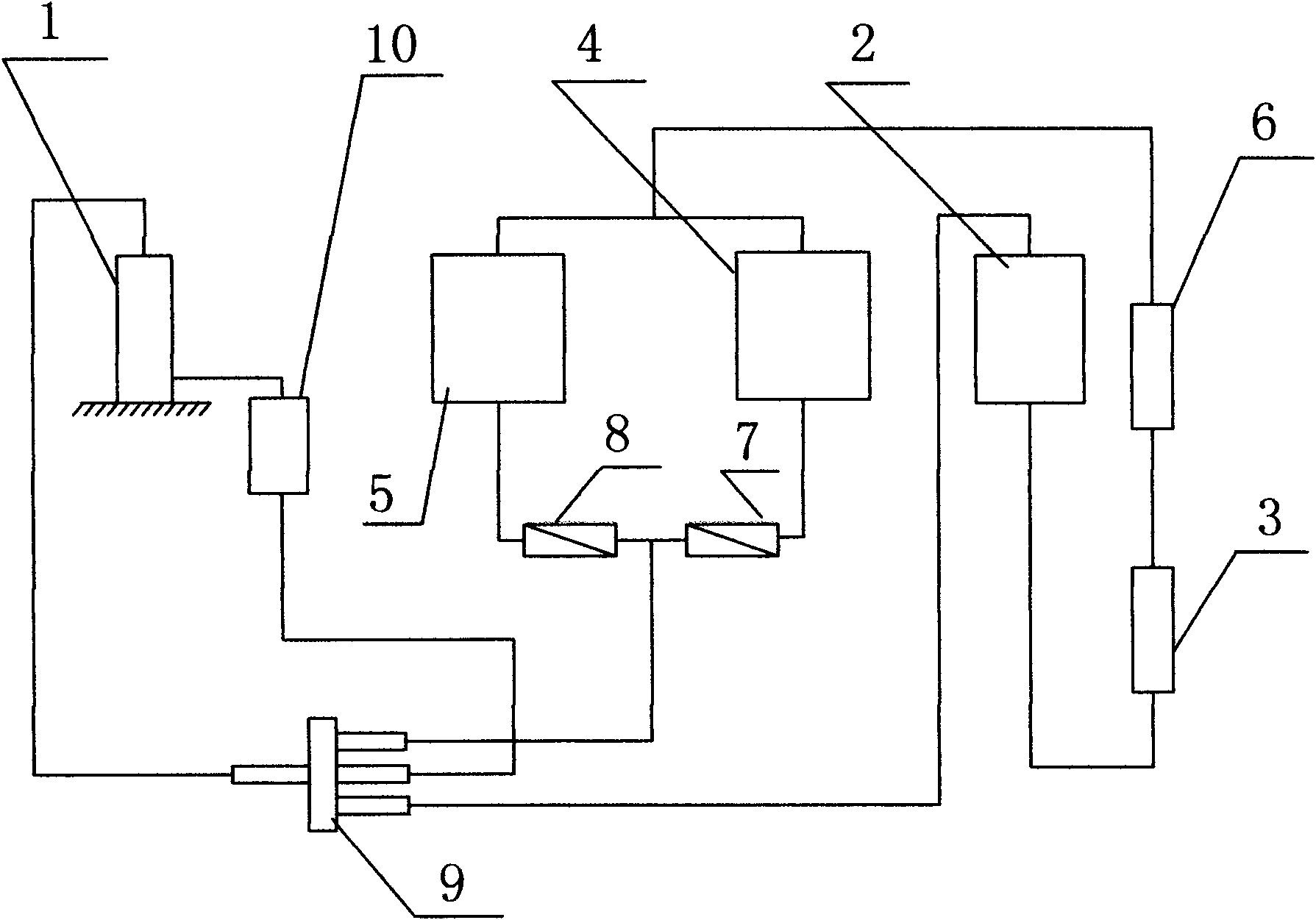
[0017] refer to figure 1 , a valve-controlled energy-saving dehumidifier, including a casing and a refrigeration system composed of a compressor 1, an evaporator 2, a condenser, a two-way filter 6, and an expansion valve 3, and the condenser includes an internal condenser 4 and The outer condenser 5 and the air inlet of the inner condenser 4 communicate with the air outlet of the evaporator 2, the condenser 4 and the outer condenser 5 are respectively connected to the expansion valve 3 through a two-way filter 6, and the inner condenser 4 is connected to the electromagnetic valve I 7, The external condenser is connected to the solenoid valve II 8, the solenoid valve I 7 and the solenoid valve II 8 are respectively connected to the four-way valve 9; one end of the compressor is connected to the four-way valve 9, and the other end is connected to the four-way valve 9 through the vapor-liquid separator 10; the evaporator 2 One end is connected to the expansion valve, and the othe...

Embodiment 2

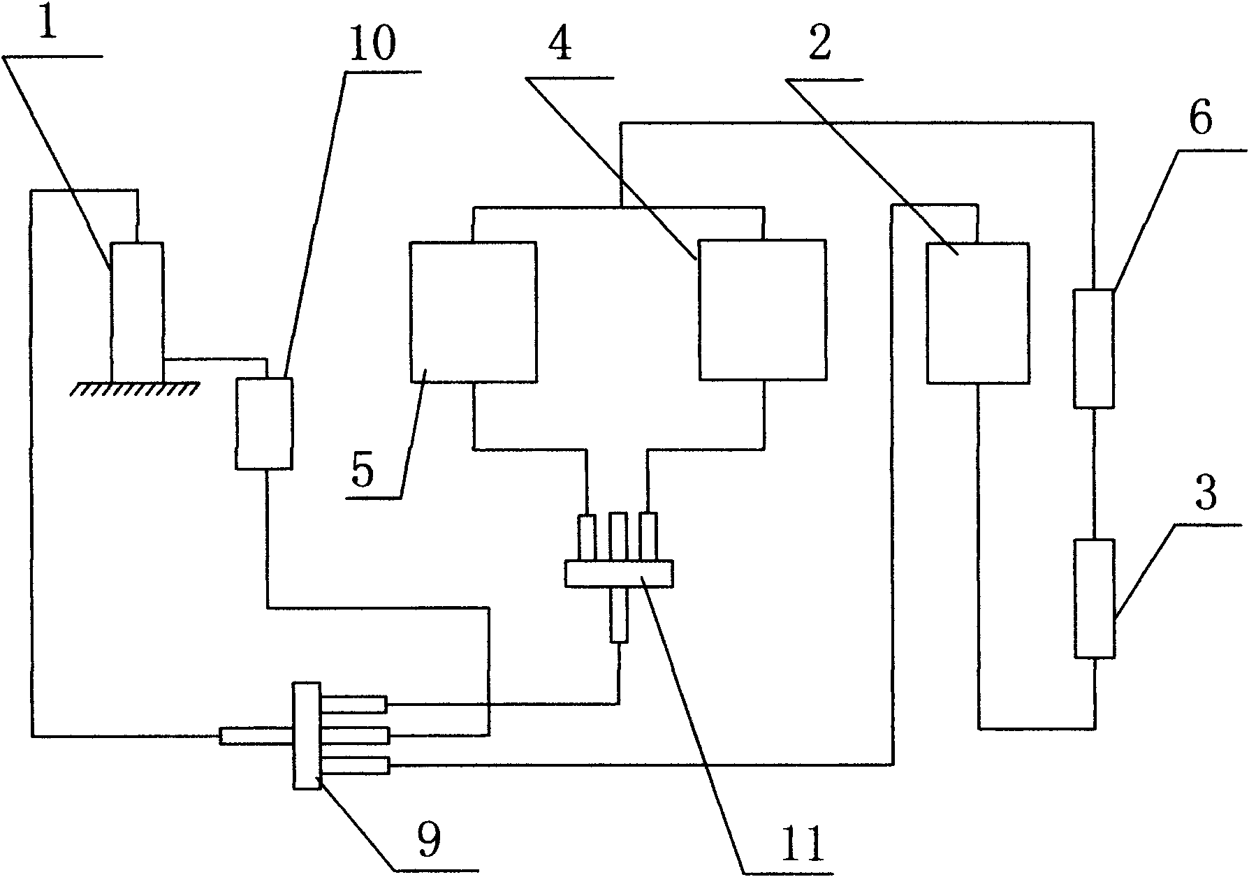
[0028] refer to figure 2 In this embodiment, the electromagnetic valve I 7 and the electromagnetic valve II 8 are replaced by a four-way valve 11, and the inner condenser 4 and the outer condenser 5 are respectively connected to the four-way valve 9 through the four-way valve 11. Others are the same as in Example 1. The inner condenser 4 and the outer condenser 5 are respectively connected to the four-way valve 9 through the control of the controller, and other working principles are the same as those in the first embodiment.


PUM


Abstract

The invention relates to a valve control type energy-saving dehumidifier comprising a shell and a refrigerating system, wherein the refrigerating system consists of a compressor, an evaporator, a condenser and an expansion valve, wherein the condenser comprises an inner condenser and an outer condenser; an air inlet of the inner condenser is communicated with an air outlet of the evaporator; the inner condenser and the outer condenser are respectively connected with the expansion valve through two-way filters; the inner condenser and the outer condenser are connected with a four-way valve (9) through reversing valves; one end of the compressor is connected with the four-way valve (9), and the other end thereof is connected with the four-way valve (9) through a gas-liquid separator; one end of the evaporator is connected with the expansion valve, and the other end thereof is connected with the four-way valve (9). The valve control type energy-saving dehumidifier not only has a dehumidification function, but also sufficiently utilizes refrigerating output and heat which are generated in the system, and can realize the effects of all-year dehumidification, summer (or high-temperature state) refrigeration and winter heating, thereby greatly reducing the energy consumption.

Description

(1) Technical field [0001] The invention relates to a valve-controlled energy-saving dehumidifier. (2) Background technology [0002] The dehumidifiers used in daily life are usually refrigeration dehumidifiers, which do not have the function of room temperature adjustment. Like air conditioners, they have a refrigeration system consisting of a compressor, an evaporator, a condenser and an expansion valve. In this system, the The compressor converts electrical energy into mechanical energy, generates high temperature and high pressure, causes the refrigerant to boil in the condenser, releases a large amount of heat energy, and completes the liquefaction of the refrigerant. Evaporation in the state, absorbing a large amount of heat energy, completing the vaporization of the refrigerant and returning to the compressor, completing the cycle of high temperature and high pressure-exothermic liquefaction-filtration and decompression-low temperature and low pressure-evaporation, he...

Claims


Application Information

Patent Timeline
IPC IPC(8): F24F1/00F25B6/02F25B41/04F24F11/02
Inventor 蒋树森
Owner 杭州松井电器有限公司
Why Eureka
Eureka Blog
Learn More