
Vortex cold vacuum aircraft engine

An aero-engine and scroll technology, which is applied to machines/engines, mechanical equipment, gas turbine devices, etc., can solve the problems of lack of independent intellectual property rights in key technologies, late start of aero-engines, and difficulty in improving, etc. The effect of many and low working resistance

Inactive Publication Date: 2010-12-29
汪一平
View PDF0 Cites 6 Cited by
  • Summary
  • Abstract
  • Description
  • Claims
  • Application Information

AI Technical Summary

Problems solved by technology

[0003] my country's aero-engines started late, although they have made enough progress, but the overall key technologies lack independent intellectual property rights, and most of them stay in the stage of plagiarism, imitation, and improvement, always lagging behind others; plus the existing traditional turbine / The turbofan engine has reached the limit due to its mechanical principle, heat engine efficiency, and engine structure, and it is difficult to improve it.

Method used


Image

  • Vortex cold vacuum aircraft engine
  • Vortex cold vacuum aircraft engine
  • Vortex cold vacuum aircraft engine

Examples


Embodiment Construction

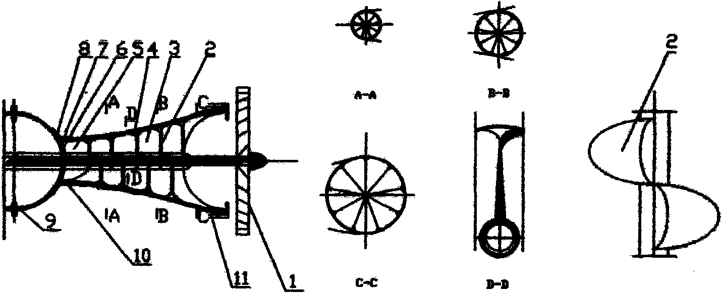
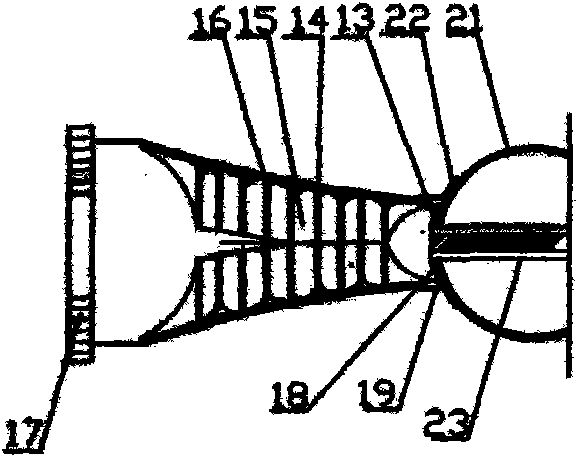
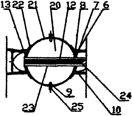
[0030] The technical solutions of the present invention will be further described in conjunction with the accompanying drawings of the above embodiments.

[0031] The working mechanism of the vortex cold vacuum aero-engine is composed of three main working processes of "(A)-(C)-(B)".

[0032] Such as figure 1 Shown is (A) schematic diagram of the working process of the vortex cold vacuum aeroengine of the present invention, transmitted by (B) machine (belonging to the active rotational force) 16, through the main transmission shaft 12, and the sheath 24 to form a three-dimensional vortex vane Road 3, the spindle rod 23 drives the (A) machine barrel 4 to rotate, so that the (A) blade road produces continuous, long-distance, long-term circumferential tangential force, radial centripetal force, and axial suction force on the gas fluid, The turbofan 1 is driven to inhale fuel and air, wherein the fuel injection controller 9 injects fuel to mix with the inhaled air, and performs t...


PUM


Abstract

The invention relates to a new generation of comprehensive and high-efficiency aircraft engine, which comprises the principles of novel three-dimensional vortex force operation, heat engine vortex cold vacuum excitation vacuum energy, thermal expansion direct conversion three-dimensional vortex force acting and the like and a novel aircraft engine structure device thereof. The invention is characterized in that (1) the three-dimensional vortex force working principle is as follow: continuous, long-time and long-distance acceleration between flow gas and multi-disc helicoradian channel in a barrel is performed so as to form strong turning moment and axial propelling effort (pressure or drawing force); (2) the heat engine uses the vortex cold vacuum to reduce a starting endpoint to be negative-pressure, vacuum and low-temperature excitation vacuum energy so as to generate powerful high-temperature, high-pressure and high-speed air flow, thereby obviously improving the working heating efficiency of the heat engine; (3) the thermal expansion is directly converted into the vortex force for acting, thereby effectively improving the working efficiency of the heat engine; and (4) a novel aircraft engine structure member design manufacturing device can improve the working efficiency of the aircraft engine. The engine of the invention has the advantages of higher efficiency, energy saving, powerful motive power, low noise, low infrared characteristics, high thermal efficiency, high thermal power conversion rate, high operating safety factors, reasonable material stress, convenient production, manufacturing and maintenance, long working life and strong flexibility of operation, can meet the requirements of variously different aircraft performances, and symbolizes a development direction of a new generation of aircraft engines.

Description

technical field [0001] The invention relates to a comprehensive and efficient new generation aero-engine. Including the three-dimensional vortex force working principle fully in line with fluid mechanics, the innovative heat engine vortex cold excitation vacuum energy and three-control six-program principle, the new vortex heat-work direct conversion principle, and its new structural device. A breakthrough in improving the thermal energy efficiency of heat engines (C 0 (Traditional heat engine heat energy)+C e (Vortex heat engine vacuum heat energy)) and heat engine work efficiency, aero-engine work efficiency. Background technique [0002] The aero engine began in 1913 when Rennes Lorrain of France proposed the design of a ramjet engine and obtained a patent. In 1930, British Frank Whittle obtained the jet engine patent, and 11 years later, the engine he designed flew for the first time, becoming the originator of the turbojet engine. After World War II, with the passag...

Claims


Application Information

Patent Timeline
IPC IPC(8): F02K3/04F02C7/00
Inventor 汪一平
Owner 汪一平
Learn More