
Taper type anti-skidding strain clamp

A tension clamp, anti-skid technology, applied in the direction of adjusting/maintaining mechanical tension, etc., can solve the problems of poor mechanical properties, plastic aging, reduction and so on

Inactive Publication Date: 2010-12-22
上海兆邦电力器材有限公司
View PDF0 Cites 6 Cited by
  • Summary
  • Abstract
  • Description
  • Claims
  • Application Information

AI Technical Summary

Problems solved by technology

However, insulated wires bring several problems during the installation of tension wires: one is the peeling installation that is costly, destroys the insulation layer, reduces the insulation safety factor, and is difficult to construct; the other is the use of wedge-shaped insulation tension clamps , its structure and performance are: open-type metal shell, installed inside the left and right plastic wedge clips with only two sides of force
This kind of wire clamp is easy to install because it does not need to strip the insulation layer of the wires, and the cost is low, but there are also big problems: because it is a metal shell with an open-mouth design, it will be under long-term tension after the strength of the metal shell is reduced during operation. The grip strength is easy to gradually decrease at the lower opening; the most important thing is the left and right plastic wedge clips, only the force on the two sides cannot guarantee a long-term effective grip on the wire, the insulation layer of the insulated wire itself has poor mechanical properties, and the tensile strength is only about 12Mpa , especially when running with electricity, when the temperature of the wire rises to about 70 degrees, its mechanical properties will be even worse. In addition, the insulation layer of the wire at the opening is exposed to the outside and it is easy to age the plastic, which will cause the insulation layer to creep and stretch. Pull out the wire core, and finally the wire clamp cannot hold the wire, causing sliding or core pulling, until the result of wire drop

Method used


Image

  • Taper type anti-skidding strain clamp
  • Taper type anti-skidding strain clamp
  • Taper type anti-skidding strain clamp

Examples


Embodiment

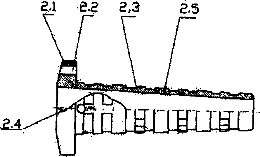
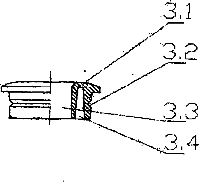
[0027] When installing and using the line, after assembling all the tapered non-slip and strain-resistant clamps as mentioned above, use the wire head or a special tool to align the inner holes of the three claws of the three anti-slip clamps and push them inward to a proper position. Because the endoporus of the conical housing 2 is tapered, the anti-slip clamping line three jaws 5 are displaced to the outside by the elastic force of three even melon springs 7, and the enlarged aperture is convenient for wire insertion. Insert the wire into an appropriate length, then release the wire tensioner, and use the tension of the wire's own weight. At this time, the three non-slip clamping claws 5, due to the action of the push melon spring 4, the three non-slip clamping claws 5 will move outwards, and at this time the anti-slip The inner threads of clamp claw 5 are tightly wrapped to hold the wire, and the greater the pulling force of the wire, due to the taper effect, the greater th...


PUM


Abstract

The invention relates to a taper type anti-skidding strain clamp applied to an electric powder overhead line terminal or a segment strain insulator-string device.The taper type anti-skidding strain clamp comprises a conical shell with binaurally assembled U-shaped pull rings at the two sides and three anti-skidding thread clamping claws, a pawl spring, an even claw spring and a tension claw spring collar arranged inside the shell.The conical shell is externally provided with a groove, the large head end surface of the shell is provided with a pressure spring end cap.The U-shaped pull ring is provided with a lengthened screw thread for fine-tuning the lead sag.The invention makes a breakthrough in an international technical difficulty and uses the most advanced circumferential packing and clamping technology to replace the internationally acknowledged two-piece clamping and pressing technology, which is of epoch-making and revolutionary significance across the world.The triple-claw clamping technology fundamentally changes ills of power grid powder transmission and distribution cables such as slippage, core loosening and the like due to two-piece cambered surface splint clamping.Being capable of solving the long-standing international defect, the invention brings unmeasurable economic benefits to the development of international power grid powder transmission and distribution.

Description

Technical field: [0001] The invention belongs to electric equipment used for power transmission and distribution overhead lines. [0002] The utility model relates to a tapered anti-slip strain clamp for clamping, fixing and suspending the tension section of the bare wire or the insulated conductor of an overhead line for power transmission and distribution. Background technique: [0003] A large number of outdated energy-consuming and strain-resistant fittings are used on power lines in my country. These fittings are basically made of malleable cast iron-based magnetic materials. , The hysteresis eddy current loss is large, and the average annual power consumption of each clamp is 500KW / h, wasting more than 200 yuan. The energy consumption is almost several times of the value of the clamp, which is completely unable to meet the needs of the modernization of the power grid. [0004] After the 1990s, my country carried out large-scale transformation of urban and rural power ...

Claims


Application Information

Patent Timeline
Patent Type & Authority Applications(China)
IPC IPC(8): H02G7/02
Inventor 王哲斐
Owner 上海兆邦电力器材有限公司
Learn More