


Quick Research
Generate reliable direction feasibility study reports for your R&D in just a few steps.

Technical Q&A
Discover and master advanced knowledge NOW. Basics, ideas, possibilities, all at once.

Find Solutions
As an expert in R&D theories, this can generate solutions to your technical problems instantly.

Evaluate Feasibility
Analyze your overall solution with one click, know your potential R&D risks in advance.

Monitor Landscape
Get weekly tech updates, stay abreast of the latest tech innovations and key insights.
Heat tube plate type radiator
A radiator and heat pipe technology, which is applied in the field of improvement of the structure of the fin type heat sink, can solve the problem of unsatisfactory heat dissipation effect, achieve the effect of good heat dissipation effect and reduce the probability of generating gas
- Summary
- Abstract
- Description
- Claims
- Application Information
AI Technical Summary
Problems solved by technology
Method used
Image

Examples
Embodiment Construction
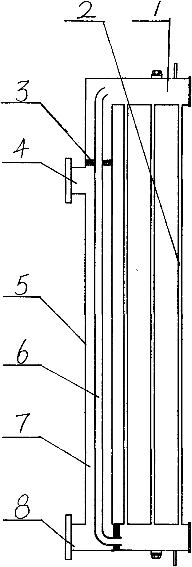
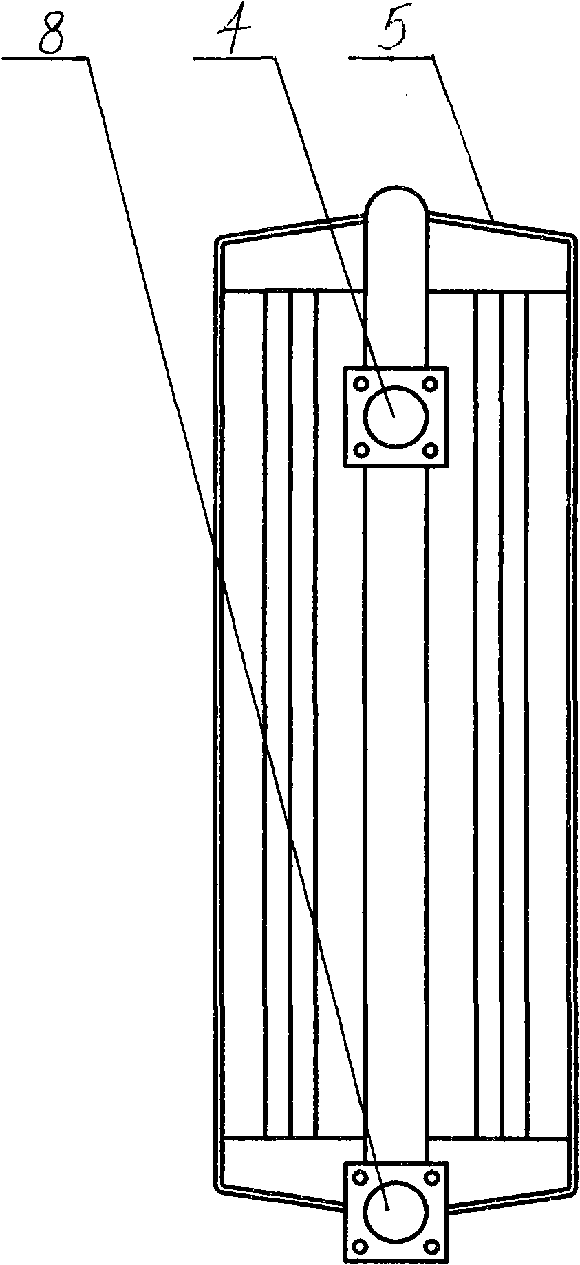
[0016] The present invention includes a body 5, which is respectively provided with an oil inlet pipe 4, a heating chamber 7, and an oil outlet pipe 8. Connected, between the delivery pipe 1 is the cooling fin 2.
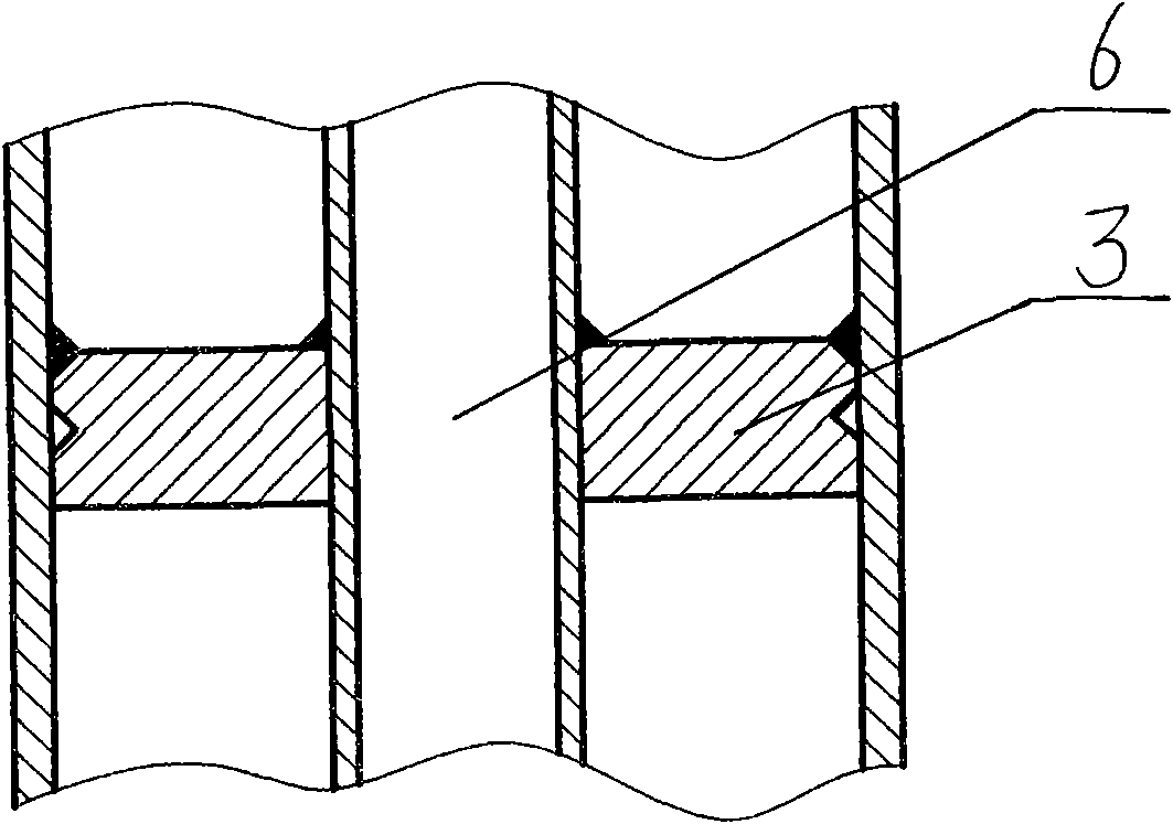
[0017] In order to enhance the heat dissipation effect of the heat sink 2 , an S-shaped guide fin 9 is arranged inside the heat sink 2 to enhance the condensation effect of the fluid in the heat sink 2 .
[0018] A partition 3 is formed between the heating chamber 7 and the delivery pipe 1 to separate the heating chamber 7 from the delivery pipe 1 .
[0019] A course of action of the present invention is illustrated below in conjunction with accompanying drawing:
[0020] When the transformer is working, its total loss makes the temperature of the transformer oil rise, and the hot transformer oil rises to the upper part of the transformer due to its low density, and flows into the oil inlet pipe 4 of the present invention, and then flows into the heating chamber 7,...
PUM
 Abstract
Description
Claims
Application Information
 - R&D Engineer
- R&D Manager
- IP Professional
- Industry Leading Data Capabilities
- Powerful AI technology
- Patent DNA Extraction
Browse by: Latest US Patents, China's latest patents, Technical Efficacy Thesaurus, Application Domain, Technology Topic, Popular Technical Reports.
© 2024 PatSnap. All rights reserved.Legal|Privacy policy|Modern Slavery Act Transparency Statement|Sitemap|About US| Contact US: help@patsnap.com