
Multi-axis linkage speed reducer

A multi-axis linkage and reducer technology, applied in mechanical equipment, transmission, transmission parts, etc., can solve the problems of complex mechanism and increased investment cost, and achieve the effect of simplifying mechanism facilities and saving investment cost.

Active Publication Date: 2010-12-22
宁波东力股份有限公司
View PDF4 Cites 4 Cited by
  • Summary
  • Abstract
  • Description
  • Claims
  • Application Information

AI Technical Summary

Problems solved by technology

[0002] In the mechanical transmission, the reducer is a machine driven by a motor to transmit the deceleration power. It is connected with the machine tool. When the machine tool involves metallurgy, mining, wood industry, mining and other fields, the traditional reducer used in it is arranged on the foundation. After the completion, it cannot be moved, so that the disadvantage that the same reducer can be used in different positions of the main machine cannot be realized, and the reducer must be re-equipped according to the requirements of different positions, resulting in complicated mechanisms and increased investment costs.

Method used


Image

  • Multi-axis linkage speed reducer
  • Multi-axis linkage speed reducer
  • Multi-axis linkage speed reducer

Examples


Embodiment Construction

[0016] Embodiments of the present invention will be described in detail below in conjunction with the accompanying drawings.

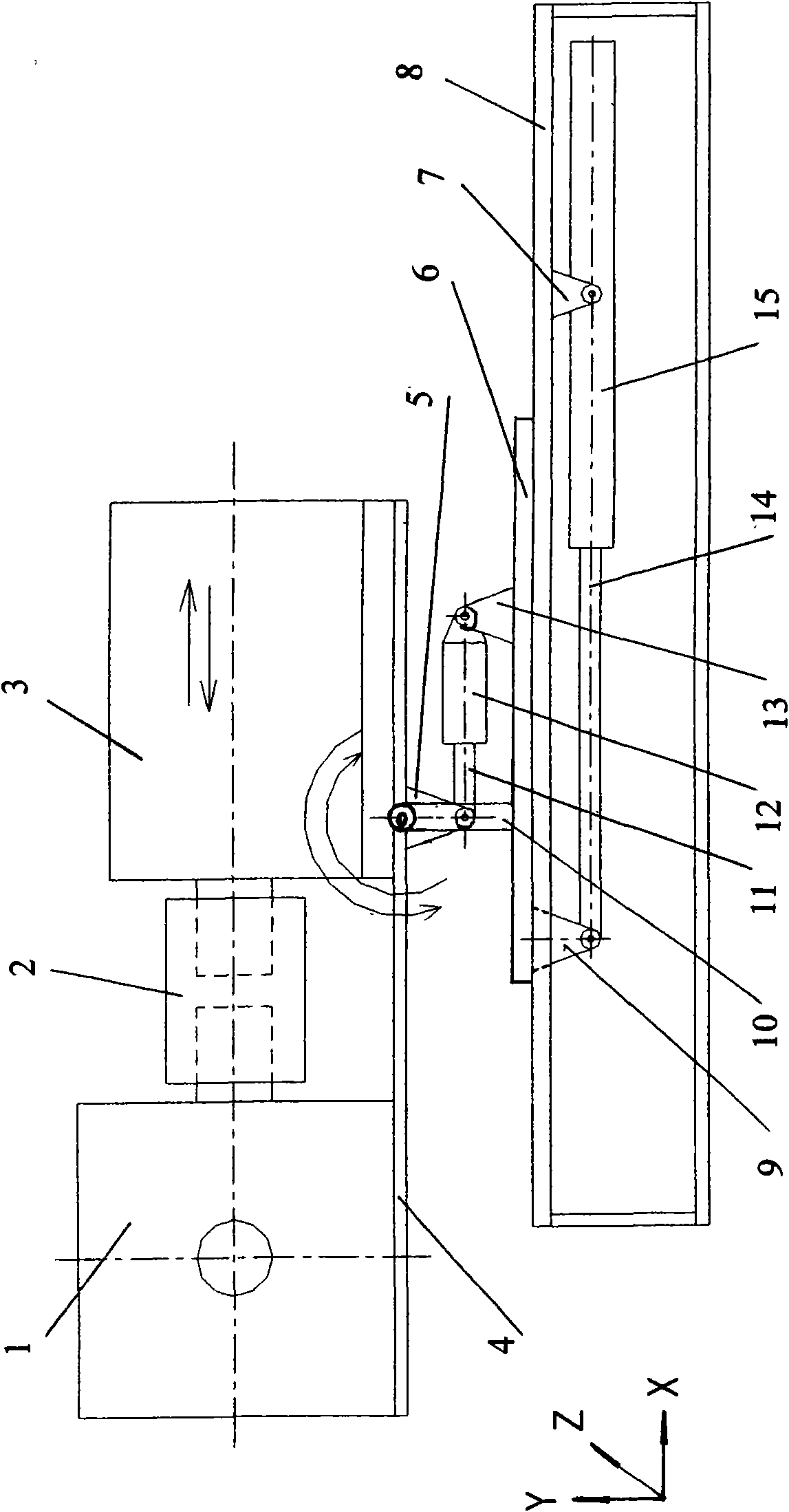
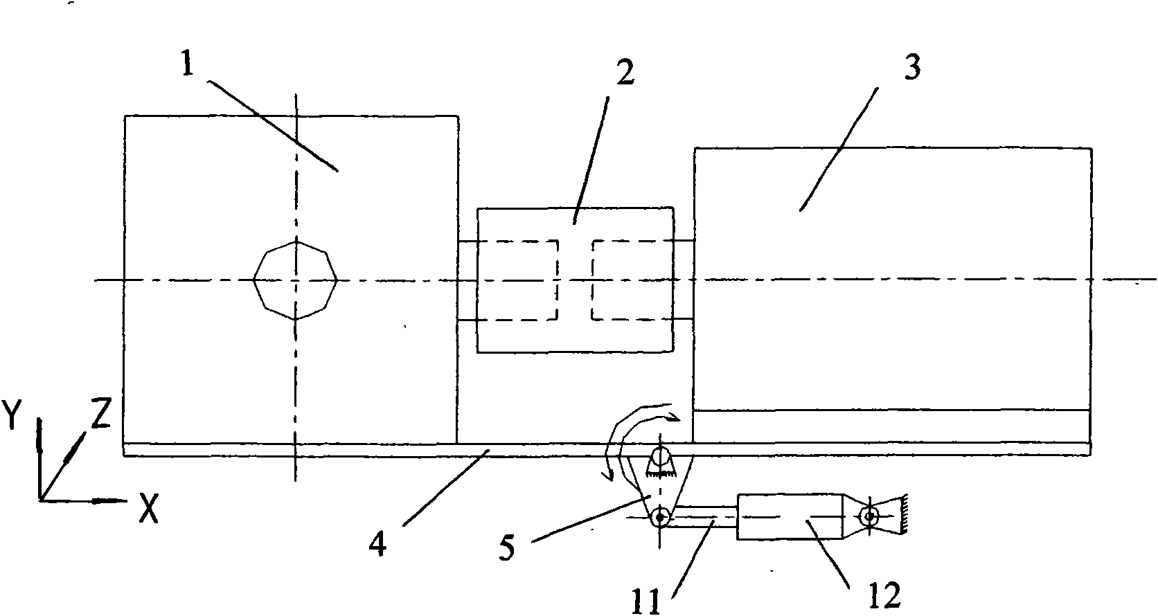
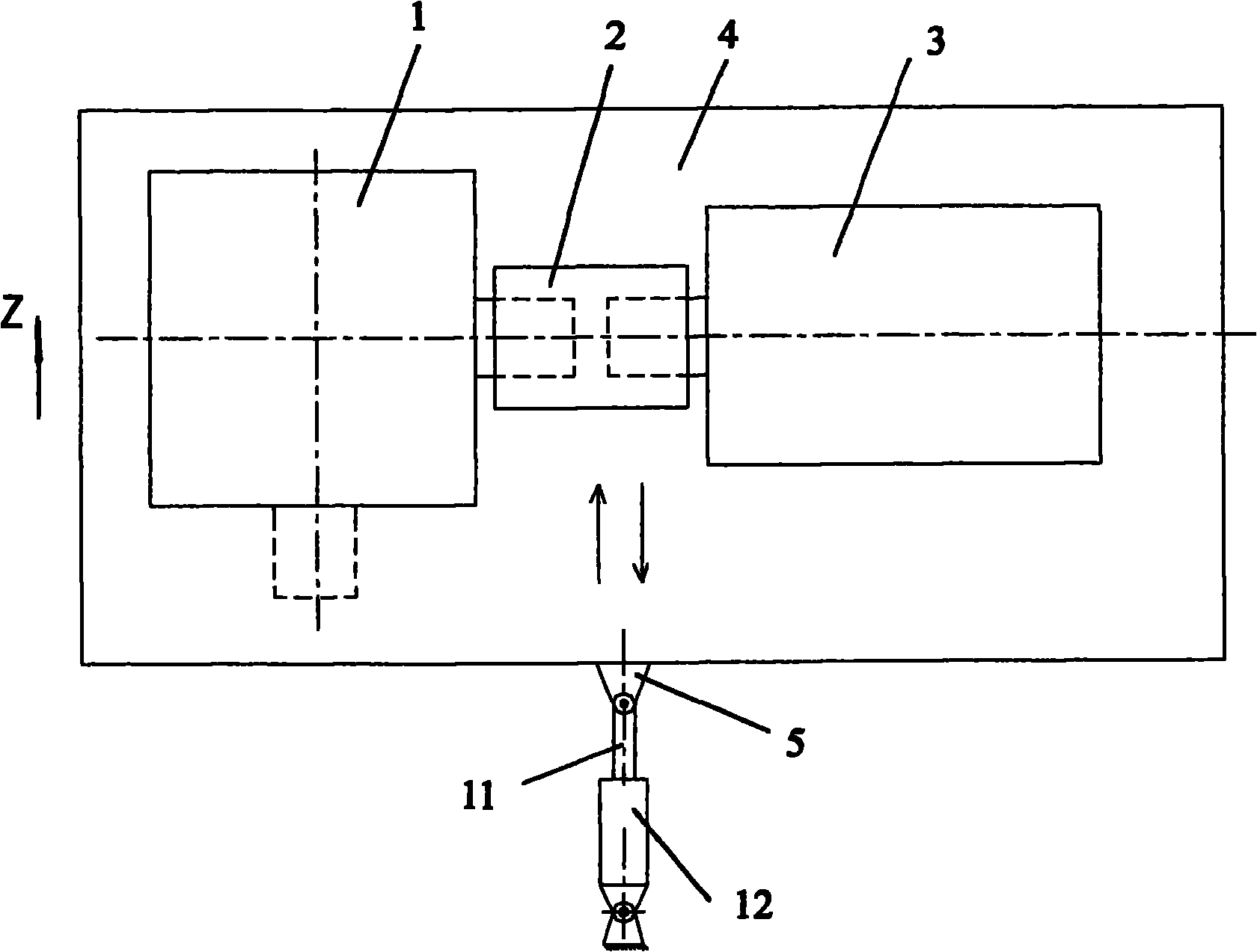
[0017] Such as Figure 1~5 As shown, in the figure 1, reducer, 2, coupling, 3, motor, 4, base, 5, first bracket, 6, first guide rail, 7, fourth bracket, 8, second guide rail, 9, Second support, 10, pole, 11, first piston rod, 12, first hydraulic cylinder, 13, third support, 14, second piston rod, 15, second hydraulic cylinder.

[0018] Such as figure 1 As shown, the reducer 1 and the motor 3 are respectively fixed on the base 4, and the reducer and the motor form a transmission connection with a coupling 2, so that the power of the motor drives the reducer to work through the coupling.

[0019] The base 4 is provided with a fixed first support 5 to support all parts on the base, the other end of the first support is hingedly connected with the first piston rod 11 in the first hydraulic cylinder 12, and the first support is connected to the base. The...


PUM


Abstract

The invention discloses a multi-axis linkage speed reducer which comprises a speed reducer, a coupling, a motor, a first bracket, a pair of support rods, a first hydraulic cylinder, a first piston rod, a first guide rail, a second guide rail, a second bracket, a third bracket, a fourth bracket, a second hydraulic cylinder, a second piston rod, and the like. By fixed or articulated connection among all parts, the speed reducer obtains power rotating around a Z axis when starting the first hydraulic cylinder; and the speed reducer obtains power moving along the direction of an X axis when starting the second hydraulic cylinder. The design concept can also realize the movement and rotation of the speed reducer along other coordinate axes by different connection among the parts. The design overcomes the defect of unavailable movement of the traditional speed reducer after foundation distribution is finished, can realize that the same speed reducer is used in different positions, saves the investment cost, simplifies mechanism facilities and is suitable for the connection drive of machine tools of special industries, such as metallurgy, mine, wood, excavation, and the like.

Description

technical field [0001] The invention relates to a speed reduction mechanism, in particular to a multi-shaft linkage speed reducer which moves along any axis and rotates around any shaft. Background technique [0002] In the mechanical transmission, the reducer is a machine driven by a motor to transmit the deceleration power. It is connected to the machine tool. When the machine tool involves metallurgy, mining, wood industry, mining and other fields, the traditional reducer used in it is arranged on the foundation. After the completion, it cannot be moved, so that the disadvantage of using the same reducer in different positions of the main machine cannot be realized, and the reducer must be re-equipped according to the requirements of different positions, resulting in complicated mechanisms and increased investment costs. Contents of the invention [0003] The purpose of the present invention is to overcome the defects of the prior art and provide a multi-axis linkage re...

Claims


Application Information

Patent Timeline
Patent Type & Authority Applications(China)
IPC IPC(8): F16H57/00F16H21/00
Inventor 陈富强宋济隆张萌王聪胡剑
Owner 宁波东力股份有限公司
Learn More