Metal strap-plate structure reactor
A metal belt and reactor technology, applied in the direction of electrode structure, electrostatic effect separation, external electrostatic separator, etc., can solve the problem of unclear physical reasons, excessive concentrations of ozone and nitrogen oxides, and inability to find micro-discharge effects, etc. problems, to achieve the effect of good insulation performance, extended working life, and simple installation process
- Summary
- Abstract
- Description
- Claims
- Application Information
AI Technical Summary
Problems solved by technology
Method used
Image
Examples
Embodiment 1
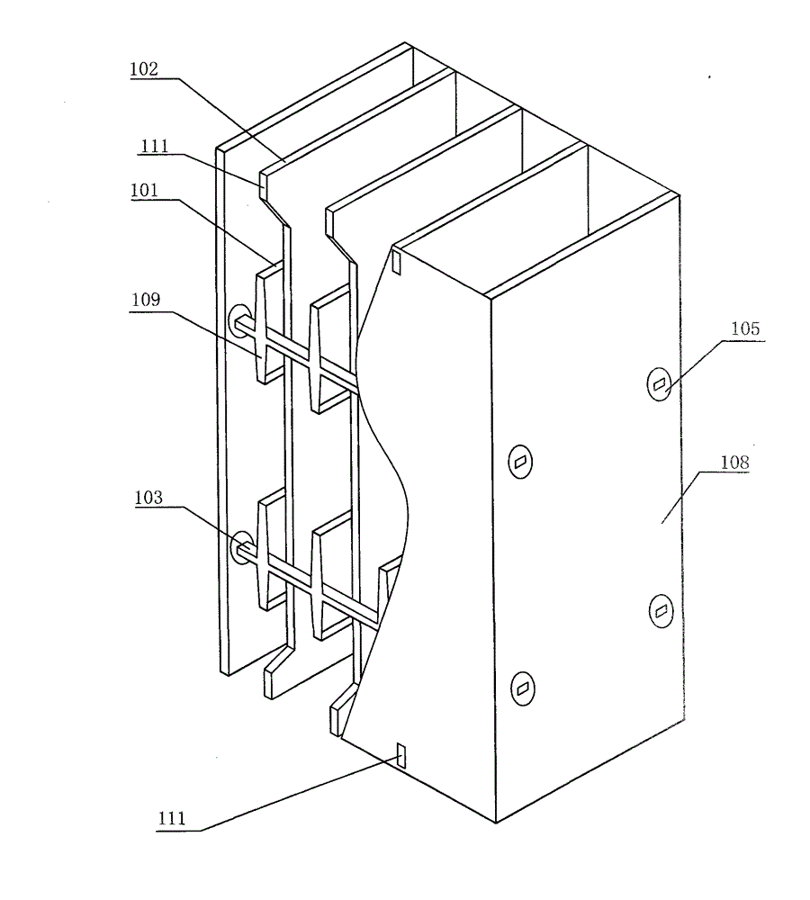
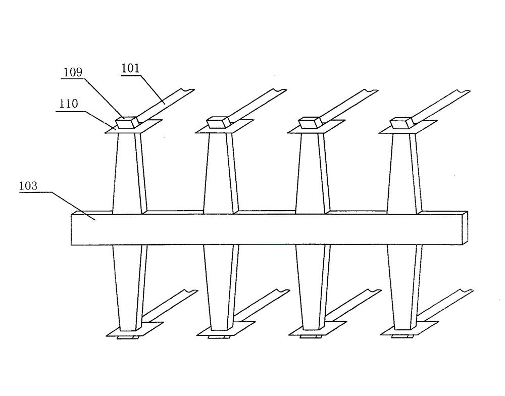
[0047] figure 1 It is a three-dimensional structure diagram including a partial section of an embodiment of the present invention; figure 2 is the invention figure 1 Schematic diagram of the structure preventing the amplification of microdischarge conducting rails.
[0048] The present invention is a metal strip-plate structure reactor, comprising a positive electrode 101, a negative electrode 102 and a metal shell 108, the positive electrode 101 is arranged in the middle of two adjacent negative electrodes 102, the positive electrode 101 and the negative electrode 102 Arranged along the airflow direction, the two sides of the negative electrode 102 are fixed on the casing 108 . The positive electrode 101 is made of several oxidation-resistant metal strips arranged in parallel at equal distances in the same plane to make a component, a total of n groups (n is an integer within 50); the negative electrode 102 is an aluminum plate or Made of stainless steel plates, a total o...
Embodiment 2
[0052] The anti-micro-discharge conductive rail 103 of the present invention is provided with convex portions 109 arranged equidistantly, and the two ends of the positive electrode 101 are respectively fixed on the top of the convex portion 109 on the corresponding conductive rail; the micro-discharge conductive rail 103 is prevented Two convex portions 109 symmetrical up and down are set as one group, each convex portion 109 for preventing micro-discharge conductive rail 103 is set as n groups, and the top of the convex portion 109 is provided with an outward bend. The two ends of the positive electrode 101 are provided with a stainless steel connection frame 110, the middle of the stainless steel connection frame 110 is punched into a square hole, and the elbow at the top of the convex part 109 is inserted into the square hole of the stainless steel connection frame 110; A protruding negative electrode fixing pin 111 is provided at each of the two ends, and is fastened with a...
Embodiment 3
[0055] Figure 4 It is a three-dimensional structure diagram of another embodiment of the present invention. The anti-micro-discharge conductive rail 103 in the figure is provided with recesses arranged equidistantly, and the recesses are provided with n groups. The two ends of the metal strip of the positive electrode 101 are respectively fixed on the corresponding recesses of the micro-discharge conductive rail 103; prevent micro-discharge conduction The two ends of the rail 103 are fixed with four positive electrode metal supports 104 which are orthogonally arranged around the reactor, and are electrically connected; the outer edge of the positive electrode metal support 104 is provided with several cylindrical conducting rails for preventing micro-discharge The fixed ring 107, the fixed ring 107 equidistantly separates the adjacent conductive rails 103 for preventing micro-discharge; the upper and lower ends of each positive electrode metal support 104 are respectively pro...
PUM
| Property | Measurement | Unit |
|---|---|---|
| width | aaaaa | aaaaa |
| thickness | aaaaa | aaaaa |
| diameter | aaaaa | aaaaa |
Abstract
Description
Claims
Application Information
 - R&D
- Intellectual Property
- Life Sciences
- Materials
- Tech Scout
- Unparalleled Data Quality
- Higher Quality Content
- 60% Fewer Hallucinations
Browse by: Latest US Patents, China's latest patents, Technical Efficacy Thesaurus, Application Domain, Technology Topic, Popular Technical Reports.
© 2025 PatSnap. All rights reserved.Legal|Privacy policy|Modern Slavery Act Transparency Statement|Sitemap|About US| Contact US: help@patsnap.com


