
Wiring base plate structure of LED signal lamp, light source assembly and LED signal lamp

A technology for wiring substrates and light source components, applied in the direction of light sources, electric light sources, point light sources, etc., can solve the problems of LED signal lights being easy to loosen in assembly and maintenance, and achieve the effects of not being easy to loosen, avoiding turning off lights, and stabilizing electrical connections

Active Publication Date: 2013-10-02
OCEANS KING LIGHTING SCI&TECH CO LTD +1
View PDF5 Cites 0 Cited by
  • Summary
  • Abstract
  • Description
  • Claims
  • Application Information

AI Technical Summary

Problems solved by technology

[0003] The purpose of the present invention is to provide a wiring substrate structure for LED signal lamps to solve the problems of assembly, maintenance and easy loosening of the above-mentioned LED signal lamps

Method used


Image

  • Wiring base plate structure of LED signal lamp, light source assembly and LED signal lamp
  • Wiring base plate structure of LED signal lamp, light source assembly and LED signal lamp
  • Wiring base plate structure of LED signal lamp, light source assembly and LED signal lamp

Examples


Embodiment Construction

[0012] In order to make the object, technical solution and advantages of the present invention clearer, the present invention will be further described in detail below in conjunction with the accompanying drawings and embodiments. It should be understood that the specific embodiments described here are only used to explain the present invention, not to limit the present invention.

[0013] The LED signal light wiring substrate structure includes a PCB substrate, and the shape and structure of the PCB substrate is center-symmetrical, such as circular, oval, triangular, square, pentagonal, hexagonal, etc. In this embodiment, a circle is selected.

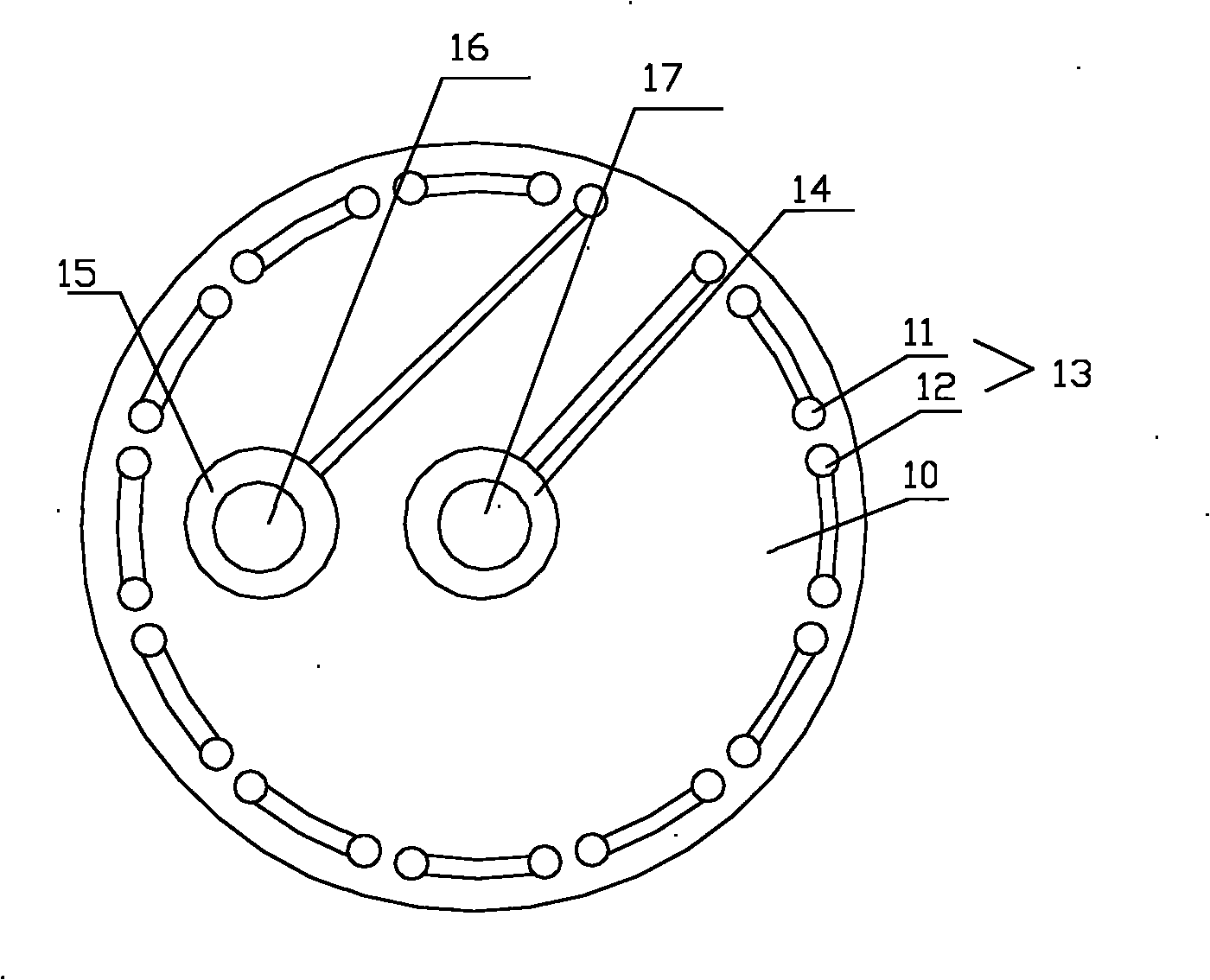
[0014] The wiring substrate structure of the LED signal light provided by the present invention adopts a single-layer PCB substrate 10 , or a multi-layer PCB substrate can also be selected according to needs. Such as figure 2 As shown, the upper surface and / or the lower surface of the periphery of the PCB substrate 10 are provided ...


PUM


Abstract

The invention is suitable for the field of electric lamps and provides a wiring base plate structure of an LED signal lamp, wherein a plurality of welding point groups used for welding an LED are arranged on an upper surface and / or a lower surface on the periphery of a PCB (Printed Circuit Board) base plate; the welding point groups comprise anode welding points and cathode welding points; a serial connecting structure is formed among all the welding points groups by wires; the starting end and the tail end of the serial connecting structure are respectively and electrically connected to an anode welding pad and a cathode welding pad which are arranged in the middle area of the PCB base plate by the wires; and the positions of the anode welding pad and the cathode welding pad are respectively provided with thorough holes. By adopting the LED signal lamp of the wiring base plate structure of the invention, the operations of assembly and maintenance are more convenient; and after the LED signal lamp is vibrated, stable electrical connection can be still formed between a conducting rod and the PCB base plate, thereby, an extinguishing phenomenon of the LED signal lamp due to power failure can be avoided.

Description

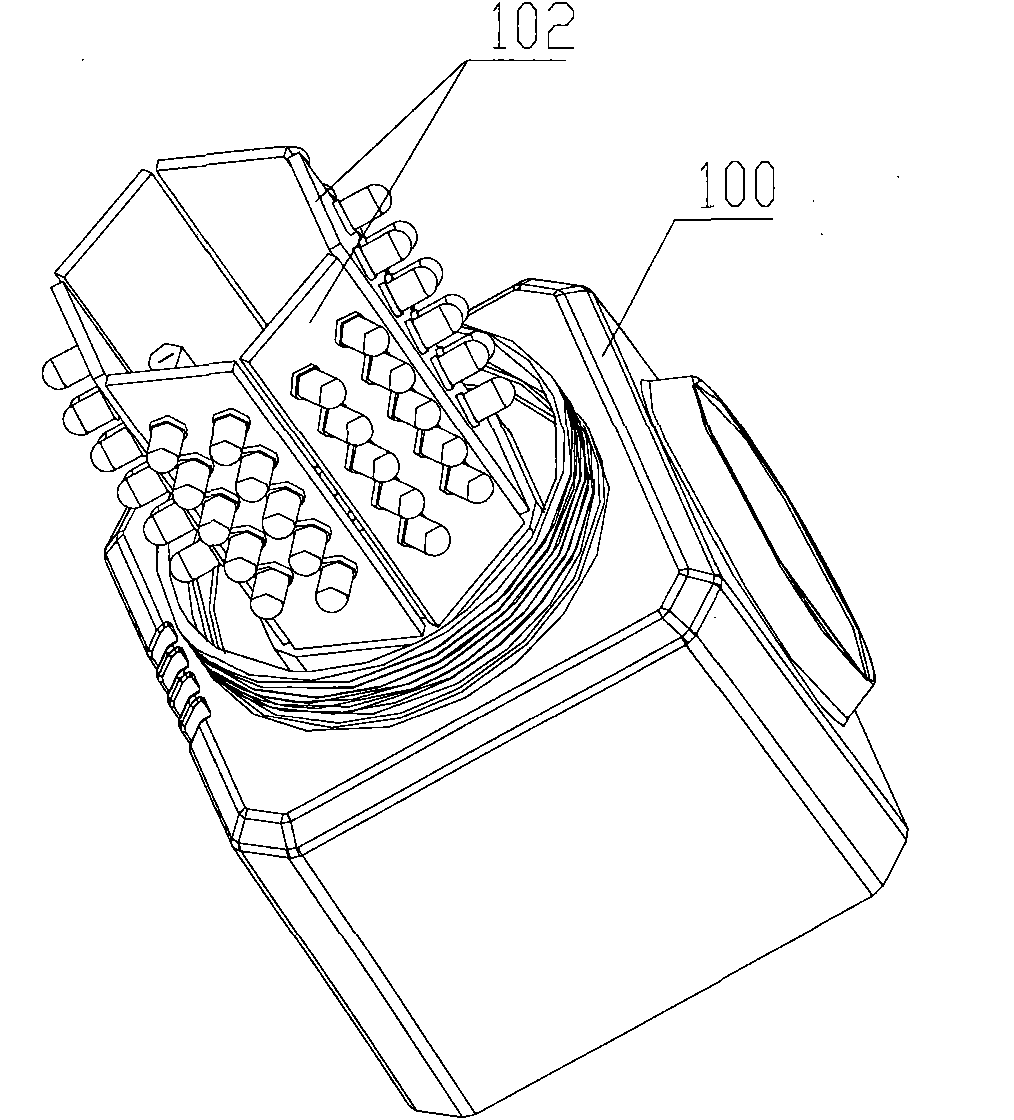
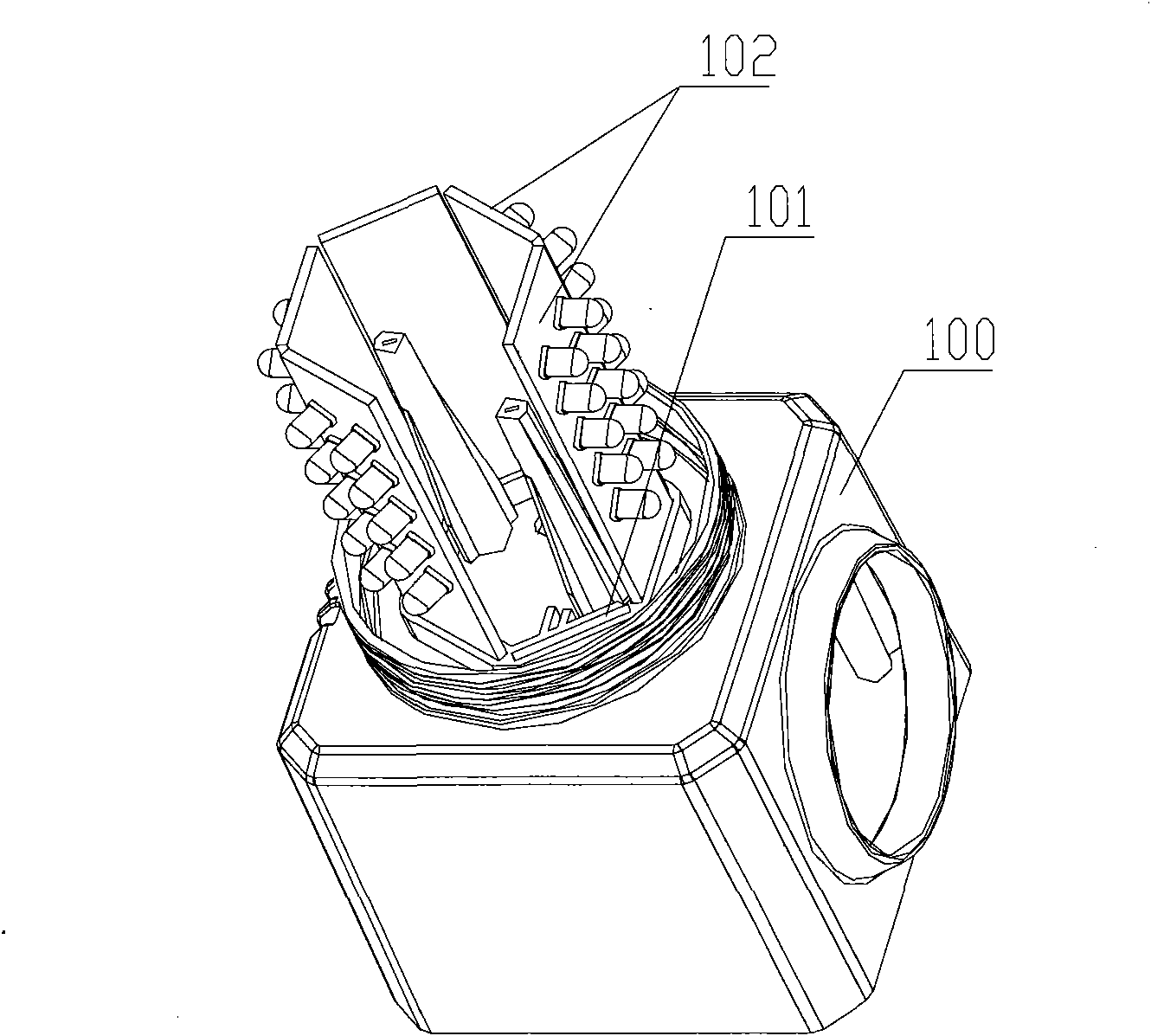
technical field [0001] The invention belongs to the field of electric lamps, and in particular relates to a wiring substrate structure of an LED signal lamp, an LED light source assembly and an LED signal lamp. Background technique [0002] LEDs are widely used in signal lamps due to their low energy consumption and long service life. Existing LED signal lights such as Figure 1a and 1b As shown, it includes a lamp body 100 and an LED light source assembly 102, and the LED light source assembly 102 is engaged with the card slot 101 provided on the lamp body 100, and the electrical connections between the LED light source assemblies 102 are connected together by wire welding. Since the LED light source assembly 102 of the existing LED signal lamp and the lamp body 100 are fixedly connected by a clamping method, the assembly operation of this fixed connection method is complicated, and it is easy to loosen when subjected to long-term vibration; and the LED light source assemb...

Claims


Application Information

Patent Timeline
Patent Type & Authority Patents(China)
IPC IPC(8): H01L33/62F21S2/00F21V23/06F21V19/00F21Y101/02
CPCF21W2111/00F21Y2107/60F21Y2115/10
Inventor 周明杰吴会利
Owner OCEANS KING LIGHTING SCI&TECH CO LTD
Learn More