
Projection-type capacitive touch screen

A capacitive touch screen, projective technology, applied in the direction of electrical digital data processing, instruments, data processing input/output process, etc., can solve the problem of increased reflected light, poor display effect and visual uniformity of the touch screen, and cannot be completely improved The appearance characteristics of the touch screen and other issues can be eliminated to eliminate the difference in reflected light intensity, the best display effect and visual uniformity, and the effect of eliminating electrode shadow

Active Publication Date: 2012-09-05
SHANTOU GOWORLD DISPLAY (PLANT II) CO LTD
View PDF0 Cites 1 Cited by
  • Summary
  • Abstract
  • Description
  • Claims
  • Application Information

AI Technical Summary

Problems solved by technology

However, this method increases the layer of the electrode, which will lead to an increase in reflected light, and will also make the outline of the electrode more obvious, so it cannot completely improve the appearance characteristics of the touch screen.
[0014] All in all, due to incident ambient light, different areas of the above-mentioned projected capacitive touch screens will have differences in reflected light intensity caused by the patterned sensing electrodes, so that when the user views the touch screen, electrode shadows appear on the surface of the touch screen (i.e. The shape and outline of the electrode), the display effect and visual uniformity of the touch screen are not good

Method used


Image

  • Projection-type capacitive touch screen
  • Projection-type capacitive touch screen
  • Projection-type capacitive touch screen

Examples


Embodiment 1

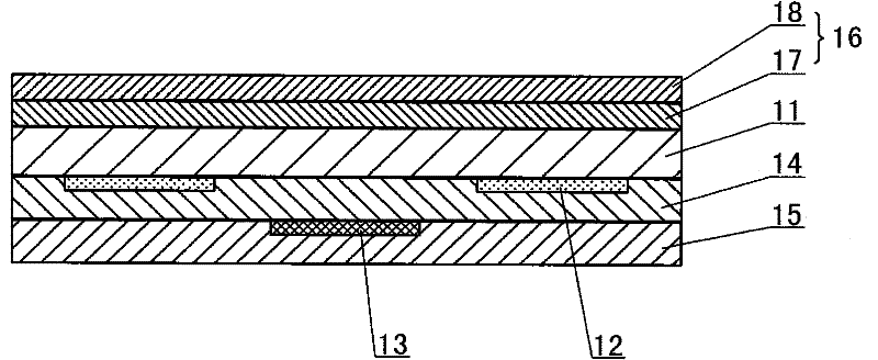
[0030] Such as figure 1 As shown, this projected capacitive touch screen includes a transparent substrate 11, on which a touch sensing component is arranged, and the touch sensing component includes a plurality of first sensing electrodes 12 extending along a first direction and a plurality of sensing electrodes 12 extending along a second direction. The second sensing electrodes 13 extending in the same direction, the first sensing electrodes 12 and the second sensing electrodes 13 are interlaced to form a sensing array, the first sensing electrodes 12 are not electrically connected to each other, and the second sensing electrodes 13 are not electrically connected to each other, and the first sensing electrodes 12 and the second sensing electrodes 13 are not electrically connected. The touch sensing part of the projected capacitive touch screen of the present embodiment has a single-sided double-layer structure, that is to say, the first sensing electrode 12 and the second se...

Embodiment 2

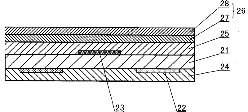
[0034] Such as figure 2 As shown, the touch sensing part of this projected capacitive touch screen is a double-sided structure, and the first sensing electrode 22 and the second sensing electrode 23 of the touch sensing part are respectively arranged on the first conductive film and the second conductive film (touch The sensing component includes a plurality of first sensing electrodes 22 extending along a first direction and a plurality of second sensing electrodes 23 extending along a second direction, the first sensing electrodes 22 and the second sensing electrodes 23 intersect each other A sensing array is formed, each first sensing electrode 22 is electrically disconnected from each other, each second sensing electrode 23 is electrically disconnected from each other, and the first sensing electrode 22 and the second sensing electrode 23 are electrically disconnected. sex is not connected), the first conductive film is on the inner side of the transparent substrate 21, a...

Embodiment 3

[0036] Such as image 3 As shown, the touch sensing part of this projected capacitive touch screen is a single-sided single-layer structure, and the first sensing electrode 32 and the second sensing electrode 33 of the touch sensing part are all arranged on the same conductive surface located on the inner side of the transparent substrate 31. film, and ensure its conduction in their respective directions through a certain bridging structure at the intersection point; the inner side of the entire touch sensing component is covered with an insulating layer 35; the outer surface of the transparent substrate 31 is attached with a polarizer 36 ( Obviously, the polarizer 36 is on the outside of the touch sensing part), the polarizer 36 contains a quarter-wave plate 37 and a polarizing layer 38, the polarizing layer 38 is on the outside of the quarter-wave plate 37, and the absorption axis of the polarizing layer 38 The included angle with the optical axis of the quarter wave plate 3...


PUM


Abstract

The invention relates to a projection-type capacitive touch screen. The capacitive touch screen comprises a transparent substrate, wherein the transparent substrate is provided with a touch inductance component; and the touch inductance component comprises a plurality of first sensing electrodes extending along a first direction and a plurality of second sensing electrodes extending along a second direction. The capacitive touch screen is characterized in that: a quarter wave plate and a polarized light layer are arranged on the outer side of the touch inductance component; the polarized light layer is positioned outside the quarter wave plate; and the included angle between an absorption axis of the polarized light layer and an optical axis of the quarter wave plate is 45 DEG. When the capacitive touch screen is used, the polarized light layer makes incident ambient light become linearly polarized light, and the quarter wave plate rotates the polarization direction of the linearly polarized light by 45 DEG. The light passes through each layer of structure on the rear side of the quarter wave plate; partially reflected polarized light is rotated by 45 DEG through the quarter wave plate; the polarization direction of the polarized light is vertical to the direction of the optical axis of the polarized light layer; the polarized light cannot pass through the polarized light layer; and the reflected light is eliminated so as to eliminate reflected light intensity difference between the different areas of the touch screen.

Description

technical field [0001] The invention relates to an input device for interaction between man and machine, in particular to a projected capacitive touch screen. Background technique [0002] In recent years, with the rapid development and application of information technology, wireless mobile communications and information home appliances, people's dependence on electronic products is increasing day by day. In order to achieve more convenience, smaller size, and more humanization, many information products have changed from traditional keyboards or mice as input devices to touch screens as input devices. Existing touch screens can be broadly classified into capacitive, resistive, and photosensitive types. Capacitive touch screens are widely used in electronic products due to their advantages of fast response time, good reliability, and high durability. [0003] Among the capacitive touch screens, the projected capacitive touch screen can realize multi-point and accurate coord...

Claims


Application Information

Patent Timeline
Patent Type & Authority Patents(China)
IPC IPC(8): G06F3/044
Inventor 吴永俊吕岳敏丁娟沈奕林钢余荣李功军孙楹煌
Owner SHANTOU GOWORLD DISPLAY (PLANT II) CO LTD
Learn More