Apparatus for removing reflected light

a technology of reflected light and apparatus, which is applied in the field of apparatus for removing reflected light, can solve the problems of not being able to partially measure suspended particles in a room, not being able to employ the wall surface structure, and being difficult for a person to know the cleanliness of a room without an instrument, etc., and achieves the effect of removing reflected light, high sensitivity and high sensitivity

Active Publication Date: 2013-07-02
SUMCO CORP
View PDF7 Cites 0 Cited by
  • Summary
  • Abstract
  • Description
  • Claims
  • Application Information

AI Technical Summary

Benefits of technology

[0027]According to the present invention, the apparatus for removing reflected light, which is used for the measuring device that emits the sheet-like beam of light onto the suspended particles and measures the light scattered from the suspended particles, is provided with the light reflective unit. This light reflective unit allows the light having traveled through the second aperture to reflect toward the predetermined direction so as to prevent the light from returning into the second aperture. Since the apparatus introduces the sheet-like beam of light and prevents the reflected light from escaping back to the outside, it is possible to remove the reflected light entering a measurement space. Therefore, the apparatus for removing reflected light according to the present invention can visualize suspended particles with high sensitivity without being affected by the environment conditions of a measurement room.
[0028]The apparatus for removing reflected light, which is used for the measuring device that emits the sheet-like beam of light onto the suspended particles and measures the light scattered from the suspended particles, includes the light absorptive unit that is irradiated with the light having entered the passage of the light introduction unit and the light sealing unit with the light absorption member confining the light reflected from the light absorptive unit. Accordingly, it is possible to remove the reflected light. Therefore, the apparatus for removing reflected light according to the present invention can visualize suspended particles with high sensitivity without being affected by the environment conditions of a measurement room.

Problems solved by technology

Since it is impossible to observe with the naked eye the suspended particles that have small diameters, it is difficult for a person to know the cleanliness of a room without an instrument.
However, it is not practical to employ the wall surface structure according to Japanese Unexamined Patent Application No. 2005-140740, for example, for measuring the cleanliness of a clean room in consideration of cost-effectiveness.
However, the abovementioned portable visualization device may have a drawback that it is only able to partially measure suspended particles in a room.
On the other hand, the abovementioned measurement device has a drawback to make the measurement of suspended particles with a high sensitivity difficult.
The reason for this is that since the emitted light travels substantially straight, the reflected light scattered on wall surfaces, obstacles and suspended particles facing the light source renders a space around a measurement object to be undesirably light.
However, as disclosed in Japanese Unexamined Patent Application Publication No. 2005-140740, there is a limitation to a certain degree for suppressing reflection and scattering of light only by a black reflective surface.
In addition, it is often difficult to actually provide a wall surface of a sufficient size in a room.
However, although a tubular element disclosed in Japanese Unexamined Patent Application Publication No. 2005-140740 can absorb light obliquely entering an aperture thereof, the tubular element can only partially absorb light entering straight the aperture by a black face disposed at a bottom of the aperture.
As a result, it is not possible to expect more from the tubular element than the effects as disclosed in Japanese Unexamined Patent Application Publication No.

Method used


Image

  • Apparatus for removing reflected light
  • Apparatus for removing reflected light
  • Apparatus for removing reflected light

Examples


first embodiment

Modification of First Embodiment

[0058]Next, a description is provided for an apparatus for removing reflected light 20 according to a modification of the first embodiment of the present invention.

[0059]Descriptions may be omitted for components bearing the same reference numerals as those used for the explanation of the first embodiment, since these components have the same features as described in the first embodiment. A first light sealing unit 4 shown in FIG. 6 is different from the first light sealing unit 3 of a cylindrical shape only in that the shape of the former is of a quadrangular tube.

[0060]According to FIG. 6, the apparatus for removing reflected light 20 is provided with a box-like light introduction unit 1, a light reflective unit 2 and a first light sealing unit 4 shaped in a quadrangular tube. The light introduction unit 1 has a slit-like first aperture 1a through which the emitted light SL enters, a second aperture 1b facing the first aperture 1a, and a passage 1c ...

second embodiment

[0071]Next, a description is provided for an apparatus for removing reflected light 30 according to a second embodiment of the present invention.

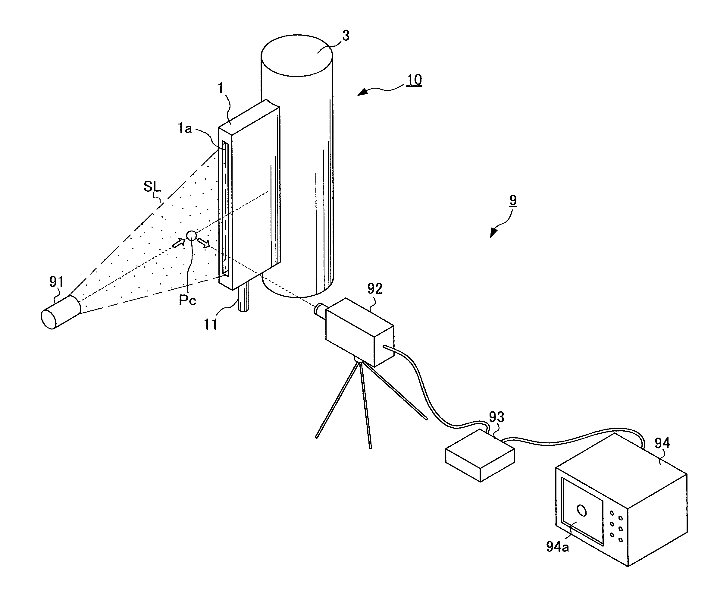
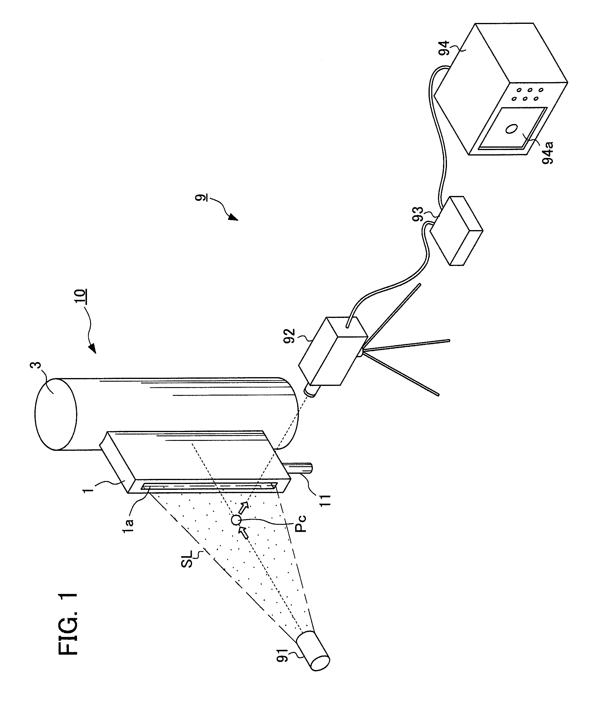
[0072]According to FIGS. 7 to 9, the apparatus for removing reflected light 30 is used for a measuring device 9 that applies the emitted light SL to suspended particles Pc and measures the light scattered from the suspended particles Pc (see FIG. 1).

[0073]According to FIGS. 7 to 9, the apparatus for removing reflected light 30 is provided with a box-like light introduction unit 1, a light absorptive unit 5a and a second light sealing unit 5 that is shaped in a quadrangular tube. The light introduction unit 1 has a slit-like first aperture 1a through which the emitted light SL is incident, a second aperture 1b facing the first aperture 1a, and a passage 1c through which the emitted light SL passes from the first aperture 1a to the second aperture 1b.

[0074]According to FIG. 9, the light absorptive unit 5a is opposite to the second aperture 1...


PUM

PropertyMeasurementUnit
particle diametersaaaaaaaaaa
imagingaaaaaaaaaa

Abstract

An apparatus for removing reflected light is provided, which is used for a measuring device that emits a sheet-like beam of light onto suspended particles and measures light scattered from the suspended particles. The apparatus includes a light introduction unit, a light reflective unit, a light sealing unit and a light absorption member. The light introduction unit has a first aperture, a second aperture, and a passage through which the light travels from the first aperture to the second aperture. The light reflective unit disposed opposite to the second aperture allows the light having traveled through the second aperture to reflect toward a predetermined direction so as to prevent the light from returning into the second aperture. The light sealing unit in which the light reflective unit is disposed has an inner wall to confine the light reflected from the light reflective unit.

Description

[0001]This application is based on and claims the benefit of priority from Japanese Patent Application No. 2009-091787, filed on 6 Apr. 2009, the content of which is incorporated herein by reference.BACKGROUND OF THE INVENTION[0002]1. Field of the Invention[0003]The present invention relates to an apparatus for removing reflected light. The present invention particularly relates to an apparatus for removing reflected light that is used for implementing visualization of particles suspended in the air with high sensitivity.[0004]2. Related Art[0005]In a factory manufacturing or employing paints, foods, films, liquid crystals, semiconductors and the like, particles suspended in the air (suspended particles) are monitored constantly, periodically or irregularly, thereby preventing unnecessary particles from contaminating or adhering to a product.[0006]Since it is impossible to observe with the naked eye the suspended particles that have small diameters, it is difficult for a person to k...

Claims


Application Information

Patent Timeline
Patent Type & Authority Patents(United States)
IPC IPC(8): H04N7/18G01N21/00
CPCG01N15/0227G01N2015/0096
Inventor EGUCHI, HIROTSUGUMATSUMOTO, MITSUHIKO
Owner SUMCO CORP
Why Eureka
Try Eureka