Eureka AIR delivers breakthrough ideas for toughest innovation challenges, trusted by R&D personnel around the world.

Bidirectional U-shaped coal-mining method of thick coal bed by gateway layout along stability layer

A coal mining method and thick coal seam technology, applied in ground mining, mining equipment, earthwork drilling and mining, etc., can solve the problems of increased section coal pillar width, difficulty in roadway excavation and support, and influence on roadway excavation speed, etc., to achieve improved The effect of improving the recovery rate, reducing the loss of coal pillars, and speeding up the excavation speed

Inactive Publication Date: 2010-12-15
TAIYUAN UNIV OF TECH
View PDF5 Cites 11 Cited by
  • Summary
  • Abstract
  • Description
  • Claims
  • Application Information

AI Technical Summary

Problems solved by technology

In the current fully mechanized mining with high mining height and top-coal caving mining, the roadways such as the upper and lower troughs and cut holes of the mining face are arranged along the coal seam floor. The obvious defect of this arrangement is that when the bottom coal seam is soft and broken, the roadway Excavation and support are very difficult; as the thickness of the coal seam increases, the width of the required section coal pillar increases
In addition, when the upper and lower grooves are arranged along the coal seam floor, it is not conducive to the discharge of gas from the working face, especially the upper corner.
[0003] In view of the above problems, the existing technology adopts advanced grouting, advanced pipe shed and advanced bolt to control the head-on roof leakage during excavation, but this seriously affects the excavation speed of the roadway, and the control effect on the stability of the surrounding rock of the roadway is not good.

Method used


Image

  • Bidirectional U-shaped coal-mining method of thick coal bed by gateway layout along stability layer
  • Bidirectional U-shaped coal-mining method of thick coal bed by gateway layout along stability layer
  • Bidirectional U-shaped coal-mining method of thick coal bed by gateway layout along stability layer

Examples


specific Embodiment approach

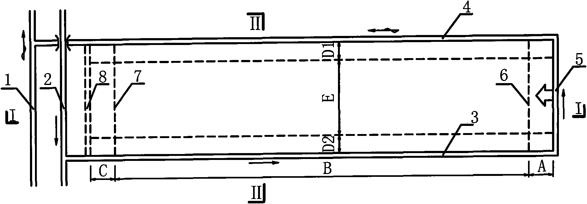
[0021] Such as figure 1 , 2 As described in 3, a schematic diagram of the mining method system of the two-way "concave" type top-coal caving working face of the present invention along the stable layer roadway distribution in thick coal seams. The roadway layout and mining technology of the two-way "concave" type top-coal caving face mining system along the stable layer with thick coal seams are as follows:

[0022] 1. Excavate along the stable layer of the thick coal seam into the air entry lane 2 of the mining area, 1 of the return air lane of the mining area, 3 of the transport trough, 4 of the return air trough, and 5 of the cutting eye, so that the roof of these roadways is a stable layer, and the mining area enters When the air lane 2 intersects with the return air channel 4, the roof of the return air channel 4 will intersect three-dimensionally above the inlet air channel 2 in the mining area to form a working face production system.

[0023] 2. The mining face forms...


PUM


Abstract

The invention relates to a bidirectional U-shaped coal-mining method of a thick coal bed by gateway layout along a stability layer. The method comprises the following steps of: firstly, tunneling all gateways of a mine along the stability layer so that top plates of the tunnels form the stability layer of the coal bed; and arranging actual mining gateways along the stability layer so that working surfaces form a bidirectional U shape along the lengths and the advancing directions, wherein a three-section actual mining process, including sapping, leveling and climbing, is adopted on the actual mining of the working surfaces along the lengths and the advancing directions. The method radically solves the difficulties in tunneling and supporting of gateway layout along soleplate in a thick coal bed in the prior art, lessens the coal pillar loss among adjacent working surfaces and is beneficial to the gas drainage of the working surfaces particularly at an upper corner. The invention is suitable for the fully-mechanized mining with large mining height and the sub-level caving mining of the loose and broken thick coal bed.

Description

technical field [0001] The invention relates to a thick coal seam coal mining method, in particular to a two-way concave-shaped coal mining method in which soft and broken thick coal seams are distributed along stable layers. Background technique [0002] Existing thick coal seam mining methods are divided into three types: layered mining, top-coal caving mining and fully-mechanized mining with large mining height. Layered mining was widely used before the 1980s. However, due to the large amount of roadway excavation, low work efficiency, high production costs and the difficulty of roadway excavation, goaf accumulation of water, natural combustion of gas and coal, etc. impact, has been less applied. Fully mechanized mining with high mining height and top-coal caving mining are the main methods of thick coal seam mining. In the current fully mechanized mining with high mining height and top-coal caving mining, the roadways such as the upper and lower troughs and cut holes o...

Claims


Application Information

Patent Timeline
IPC IPC(8): E21C41/16E21D9/00E21D9/14
Inventor 康天合郭灵飞柴肇云代金华
Owner TAIYUAN UNIV OF TECH
Why Eureka
Eureka Blog
Learn More