Distribution packagaing body

A packaging body and cover technology, applied in packaging, wrapping paper, transportation and packaging, etc., can solve the problems of oxidative deterioration and insufficient oxygen barrier properties, and achieve the effect of improving oxygen barrier properties

Inactive Publication Date: 2010-12-08
Q P CORP
View PDF14 Cites 0 Cited by
  • Summary
  • Abstract
  • Description
  • Claims
  • Application Information

AI Technical Summary

Problems solved by technology

[0003] However, the oxygen barrier properties of these synthetic resins listed as specific examples are not sufficient, so there is a concern that the contents of the distribution package may be oxidatively deteriorated due to oxygen penetrating through the cap.

Method used


Image

  • Distribution packagaing body
  • Distribution packagaing body
  • Distribution packagaing body

Examples


Embodiment 1

[0100]

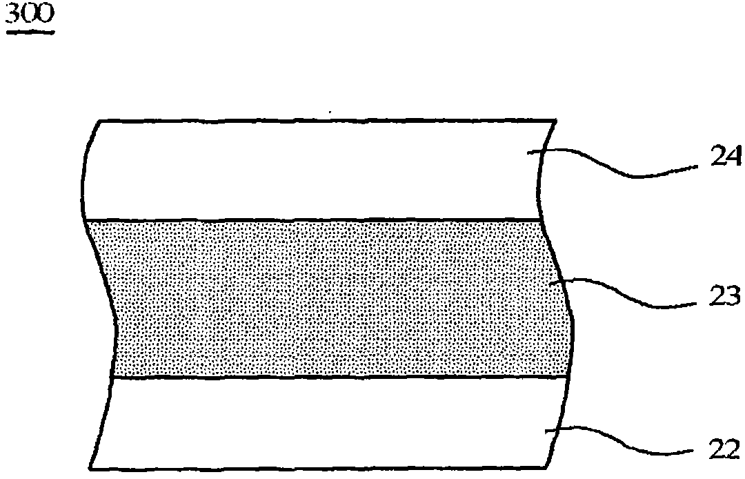
[0101]PET(20μm) / AD(10μm) / EVOH(20μm) / AD(10μm) / HIPS[50% by mass]+GPPS[50% by mass](300μm) / AD(10μm) / LDPE[50% by mass]+HDPE [50% by mass](10μm) / LDPE(10μm)

[0102]

[0103] Ny(20μm) / EVOH(50μm) / AD(20μm) / LDPE(20μm)

[0104] The hard composite sheet and the flexible composite film of the above-mentioned layer structure are produced by a co-extrusion method.

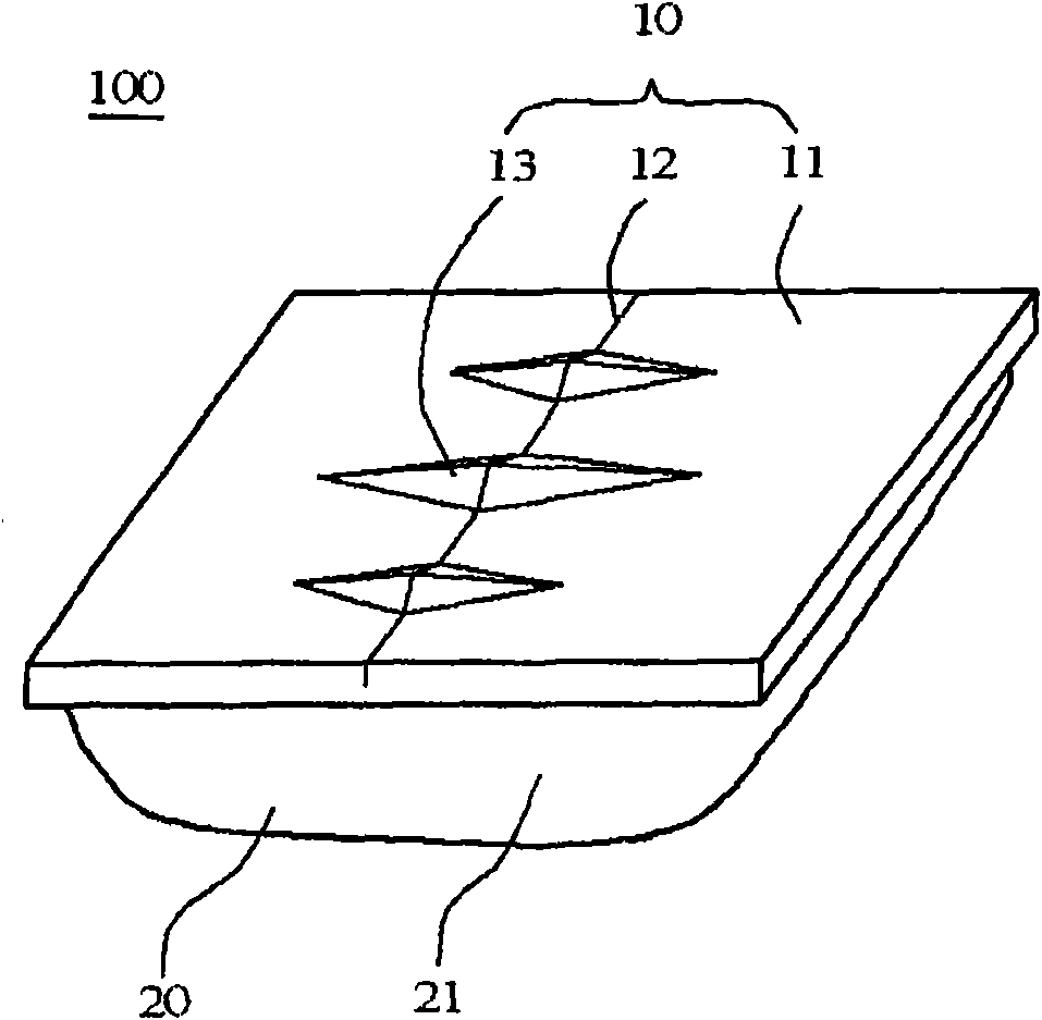
[0105] Next, at a predetermined position of the hard composite sheet, the PS layer was cut from the side of the PET layer to a depth of 50% of its thickness, and half-cut was performed on the hard composite sheet. Next, the half-cut hard composite sheet was heat-formed by a mold forming method to form a convex strip that forms a discharge port for discharging the contents.

[0106] On the other hand, the flexible composite film is deep-drawn to form a pocket. After filling the bag portion with mayonnaise (manufactured by Kuipi Co., Ltd.) as a liquid food, it was combined with the hard composite sheet on which the...

Embodiment 2

[0112] Dispensing packaged food (mayonnaise) was produced in the same manner as in Example 1 except that the thickness of EVOH in the rigid composite sheet of Example 1 was changed from 20 μm to 10 μm. The layer structure of the rigid composite sheet used is shown below.

[0113]

[0114] PET(20μm) / AD(10μm) / EVOH(10μm) / AD(10μm) / HIPS[50% by mass]+GPPS[50% by mass](300μm) / AD(10μm) / LDPE[50% by mass]+HDPE [50% by mass](10μm) / LDPE(10μm)

Embodiment 3

[0120]

[0121] PET(20μm) / / EVOH(20μm) / / HIPS[80% by mass]+GPPS[20% by mass](300μm) / AD(10μm) / LDPE(10μm) / LDPE(10μm)

[0122]

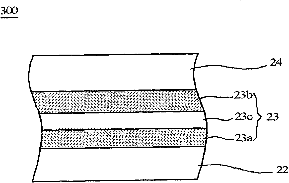
[0123] Ny (20 μm) / EVOH [92% by mass] + oxygen-absorbing resin [8% by mass] (50 μm) / AD (20 μm) / LDPE (20 μm)

[0124] A rigid composite sheet having the above-mentioned layer structure is produced by combining the co-extrusion method and the dry lamination method. In addition, the above-mentioned flexible composite film was produced by a coextrusion method. The oxygen barrier layer of the flexible composite film is located in the range of 18 to 64% from the outer surface of the surface protection layer with respect to the thickness of the flexible composite film.

[0125] Using the above-mentioned rigid composite sheet and flexible composite film, the same method as in Example 1 was used to manufacture a packaged food for distribution (mayonnaise).


PUM

PropertyMeasurementUnit
thicknessaaaaaaaaaa
thicknessaaaaaaaaaa
thicknessaaaaaaaaaa

Abstract

The invention relates to an allocation packaging body, which has an allocation packaging body having a structure of welding container body of flexible member on the hard material cover, which does not prevent oxygen permeation from the cover at a higher level with opening, the cover has folding lines of half cutting part and a convex part formed with outlet opening on the central part of the surface. The allocation packaging body has a hard casing, and a flexible container body, the allocation packaging body is formed by welding a periphery part of the flexible container body on the back face of the hard casing, the hard casing, in the surface central part, has folding lines of half cutting part formed by the surface side and a convex part formed with outlet opening, and a convex part formed with an discharge port during bending, the flexible container body has a bag part for housing the content object, in the allocation packaging body, the hard casing is formed by hard complex sheet materials, the hard complex sheet is formed by laminating in sequence a printing receiving layer, a hard central layer and a casing sealing layer. The hard central layer has a polystyrene resin layer and a ethylene-vinyl alcohol copolymer resin layer configured at the printing receiving layer side.

Description

technical field [0001] The present invention relates to a dispensing package for packaging various liquids and pastes. Background technique [0002] Dispensing packages are known in which the filled contents (such as jam, ketchup, ketchup, etc.) can be extruded by the simple operation of bending the lid with one hand and squeezing it in this state. liquid food such as dressing) (Patent Document 1). The dispensing package has a structure in which the lid of the hard material is welded to the container body of the flexible member, wherein the lid of the hard material has a bending line provided with a half-cut portion (Halfcut portion) at the center of the surface, and is used When bent, the convex portion of the discharge port is formed, and the container body of the flexible member forms a pocket portion (pocket portion) for storing the contents. In addition, specific examples of the hard material constituting the cap include polyethylene, polyethylene terephthalate, and p...

Claims


Application Information

Patent Timeline
Patent Type & Authority Applications(China)
IPC IPC(8): B65D77/20B65D65/40B65D85/72B32B27/08B32B27/28B32B27/32B32B3/14
CPCB32B27/08B32B27/302B32B27/306B32B27/32B32B27/36B32B2307/7244B32B2307/75B32B2435/02B65D75/36B65D75/585B65D85/72
Inventor 室塚聪子野田治郎
Owner Q P CORP
Why Eureka
Try Eureka