Ejection blow molding method for making transparent plastic material water ball container and finished water ball container thereof

An injection molding and water polo technology, which is applied to the injection blow molding method of transparent plastic water polo containers and the finished products of water polo containers, can solve problems such as unevenness, achieve good appearance, increase acceptance and purchase desire, and increase quality Effects on sex and worth

Inactive Publication Date: 2013-05-15
蔡瑞安
View PDF0 Cites 1 Cited by
  • Summary
  • Abstract
  • Description
  • Claims
  • Application Information

AI Technical Summary

Problems solved by technology

However, in terms of prior art, the injection port 21a of the injection molding mold 20a is located at the center of the top bullet head of the cap-shaped mold base 30a such as Image 6 As shown, its main purpose is to make the internal stress of the cap-shaped mold base 30a relatively uniform after injection molding, so as to facilitate the subsequent blow molding process, that is, to avoid spherical shape after blow molding due to uneven internal stress. The thickness of the part 11a is uneven; but such a design forms an obvious injection mark 31a at the center of the top bullet head of the injection-molded cap-shaped mold base 30a such as Figure 7 As shown, and after the blow molding process, the top of the finished product of the formed water polo container 10a, that is, the top center of the spherical part 11a, will still remain and cause an obvious injection mark 13a such as Figure 5 As shown, it seriously affects the appearance of the finished product of the water polo container 10a; and when the blow molding process is carried out, the blow molding molds (not shown) used in the prior art are generally made of left and right symmetrical molds with hemispherical mold cavities. The two halves of the mold are tightly connected, and the joint surface of the two halves of the mold is a common parting line; however, in order to make the blowing molding process smoother, the blown air can evenly stretch the mold base 30a In order to smoothly blow and form the spherical part 11a of the water polo container 10a in the blow molding mold, the prior art often intentionally makes the interface between the two half molds (i.e. the parting line) form a small gap as an exhaust gas. Holes are used so that the original air in the mold cavity of the blow molding mold can leave the mold cavity through the gap between the interface joint surface (parting line) along with the blow molding (expansion) of the spherical part 11a, so as to avoid failure due to failure. Exhaust relatively forms air resistance and hinders the normal expansion of the spherical part 11a during blow molding; yet, the micro gap formed at the junction of the two half-moulds in the prior art is relatively spherical after blow molding. A relatively obvious parting line 14a is formed on the surface of part 11a such as Figure 5 As shown, it affects the appearance of the finished product of the water polo container 10a; as can be seen from the above, the finished product of the water polo container 10a made by the prior art not only has obvious injection marks 13a in the center of the surface top of the spherical part 11a, but also has a There is an obvious parting line 14a in the meridian direction of the surface of 11a, which greatly affects the appearance. Therefore, the appearance quality of the existing transparent plastic water polo container 10a is far inferior to the existing glass water polo, which affects its sense of value, so it cannot effectively meet the needs of consumers. acceptability and purchase desire

Method used


Image

  • Ejection blow molding method for making transparent plastic material water ball container and finished water ball container thereof
  • Ejection blow molding method for making transparent plastic material water ball container and finished water ball container thereof
  • Ejection blow molding method for making transparent plastic material water ball container and finished water ball container thereof

Examples


Embodiment Construction

[0025]The above and other technical features and advantages of the present invention will be described in more detail below in conjunction with the accompanying drawings.

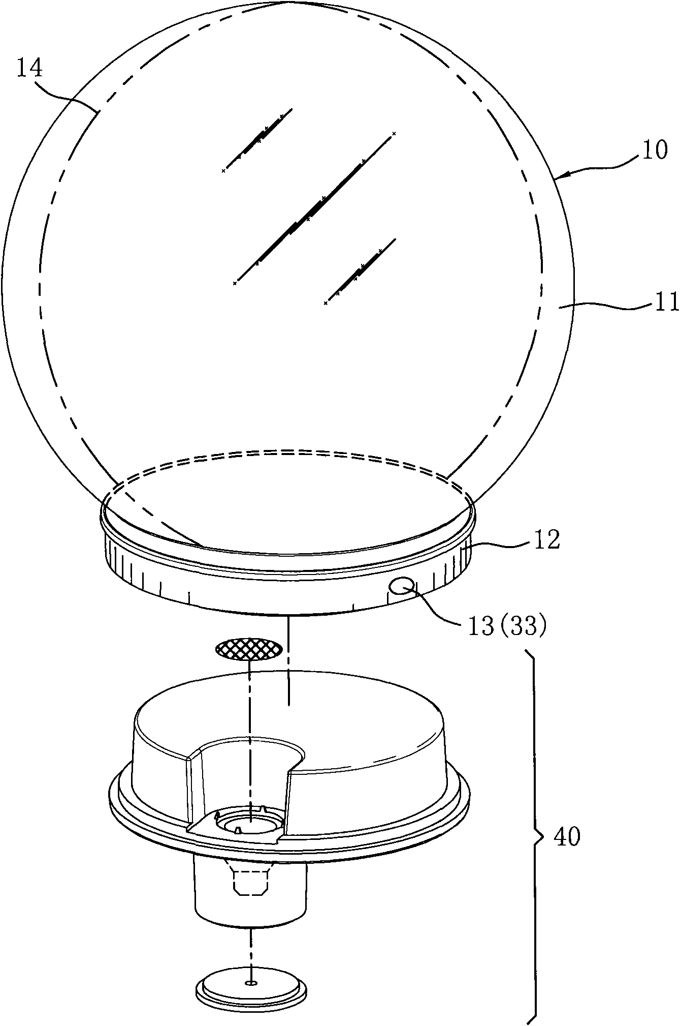
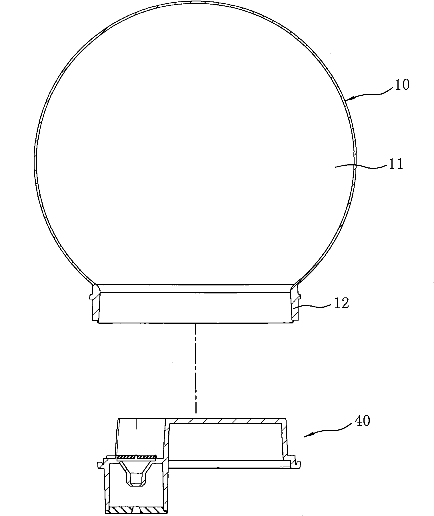
[0026] refer to figure 1 , 2 , the present invention utilizes plastic material to make a transparent plastic material water polo container 10 such as figure 1 As shown, the transparent plastic material used therein includes PC (polycarbonate, Polycarbonate) or acrylic resin (Acrylic resin); The finished product of the water polo container 10 includes a spherical part 11 and a circular neck part 12, In addition, a bottom cover 40 is used to lock and close the neck portion 12 of the water polo container 10 to form an airtight container, wherein the locking method of the bottom cover 40 is not limited, and this embodiment is combined by ultrasonic welding.

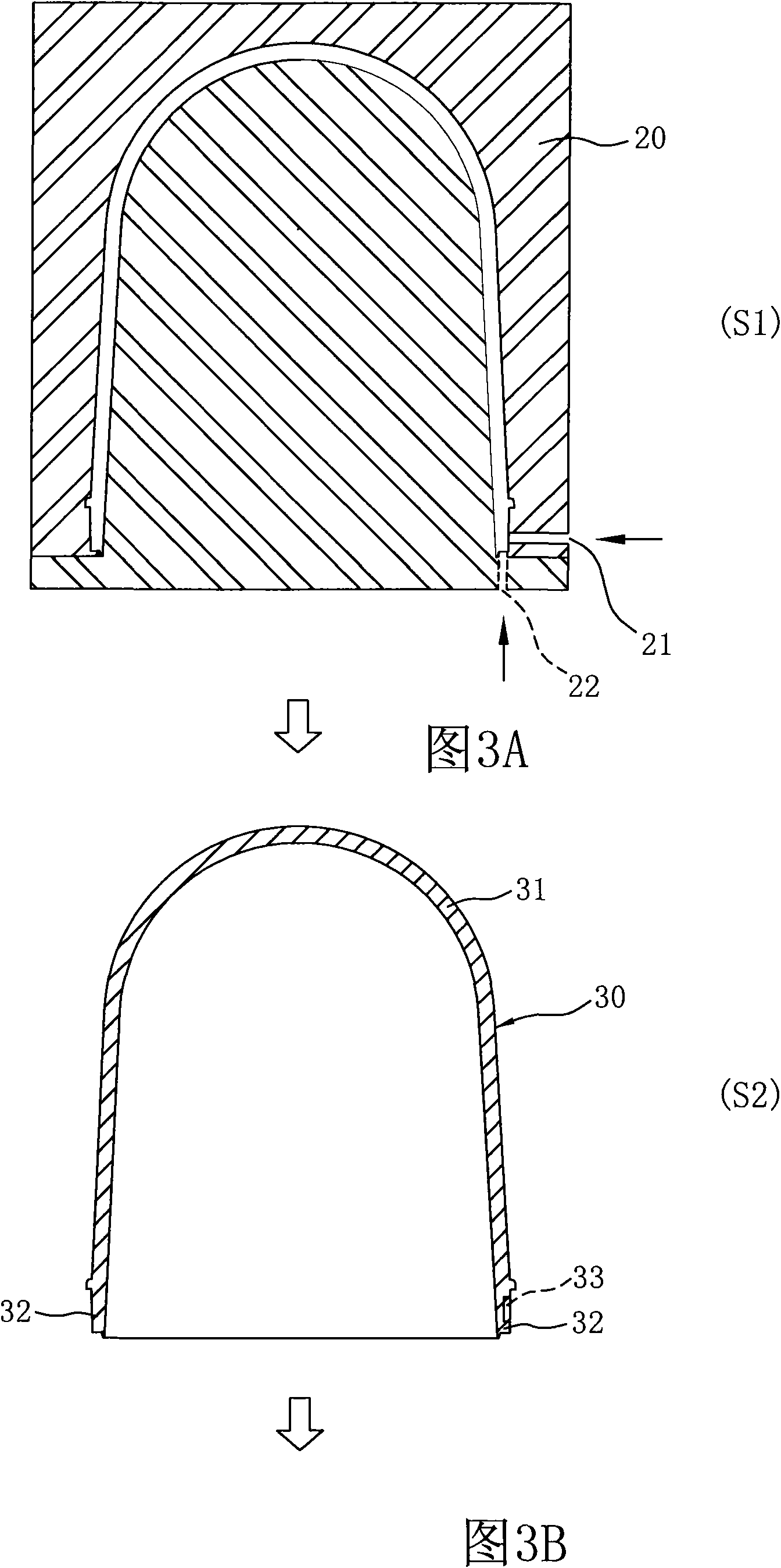
[0027] refer to Figure 3A-3F Shown, the injection blow molding (injection blow) manufacturing method of transparent plastic water polo container 10 ...


PUM


Abstract

The invention relates to an ejection blow molding method for making a transparent plastic material water ball container and a finished material water ball container thereof. The method comprises the following steps: making a cap-shaped die blank with an elastic head from a transparent plastic material, such as PC or acryl resin, by using an ejection molder, wherein the ejection-molded filling port is arranged at the neck part of the bottom of the cap-shaped die blank, and the neck part is already set at the time of ejection molding; before blow molding, softening the plastic material die blank by heating to deformation temperature, such as 90-120 DEG C; and moving the softened plastic material molded blank to a blow molding die, and clamping the neck part to blow air, so that the die blank above the neck part is molded into a spherical part, thereby obtaining the finished water ball container, wherein the blow molding die is provided with at least one vent hole in the position near the neck part, i.e. two vent holes are symmetrically arranged at the loop edge arc position near the neck part. The method can be used for making blow-molded water ball containers, and the water ball container has good appearance like a glass water ball.

Description

technical field [0001] The present invention relates to an injection blow molding method of a transparent plastic water polo container and the finished product of the water polo container, especially to a cap-shaped mold blank with a bullet-shaped head made by an injection molding machine, and then injection-molded The injection port is located at the neck portion of the bottom of the cap-shaped mold base, and at least one vent hole is provided at the position close to the neck portion of the blow molding mold, so that the finished product of the blow-molded water polo container can It has a good appearance like a glass water polo, so as to avoid the disadvantages that the spherical part of the transparent plastic water polo container made by the prior art has obvious injection marks and parting lines that affect the appearance. Background technique [0002] Airtight liquid decorations such as common water polo are a traditional gift, and their structure generally includes a...

Claims


Application Information

Patent Timeline
Patent Type & Authority Patents(China)
IPC IPC(8): B29C49/06
Inventor 蔡瑞安
Owner 蔡瑞安
Why Eureka
Try Eureka