
Dual computer hot-standby system of LED display screen

A technology of LED display screen and dual-system hot backup, which is applied to components, static indicators, TVs, etc. of TV systems to reduce the probability of manual maintenance and improve stability and reliability.

Active Publication Date: 2010-11-24
CHANGCHUN CEDAR ELECTRONICS TECH CO LTD
View PDF4 Cites 16 Cited by
  • Summary
  • Abstract
  • Description
  • Claims
  • Application Information

AI Technical Summary

Problems solved by technology

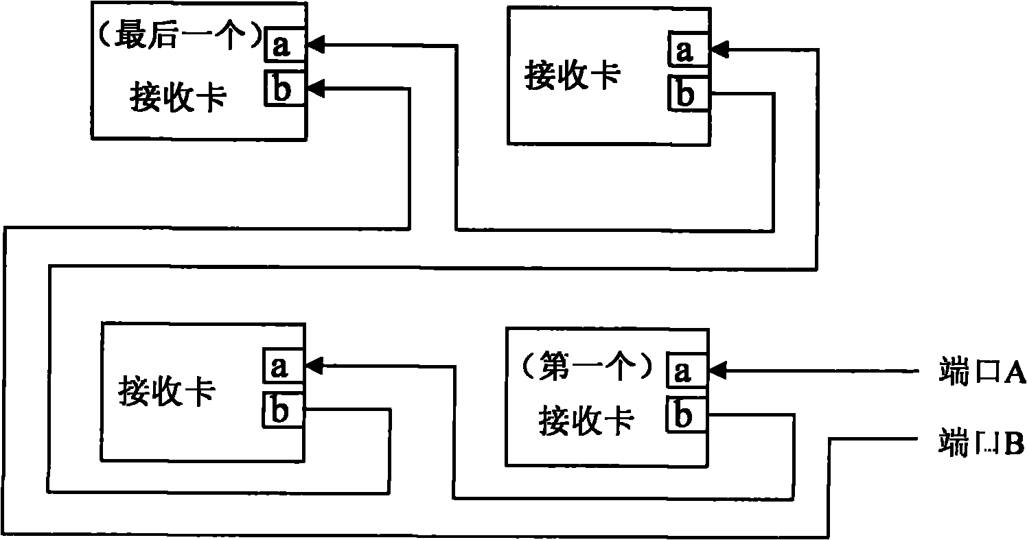
[0004] The technical problem to be solved by the present invention is to provide a LED display dual-computer hot backup system that can still adaptively restore the data path when multiple links of the LED display control system have problems at the same time, so that the video display is not affected

Method used


Image

  • Dual computer hot-standby system of LED display screen
  • Dual computer hot-standby system of LED display screen
  • Dual computer hot-standby system of LED display screen

Examples


Embodiment 1

[0043] The video source adopts two independent hosts 191,192, and the video transmission device adopts Gigabit network sending cards 111,112, requiring the video sources in the two independent hosts 191,192 to be completely synchronized in real time, as Figure 11 shown. This scheme realizes the double backup of the host computer and further improves the stability of the system. Of course, real-time synchronization of video sources requires additional equipment to control the two hosts.

[0044] The block diagram of LED display dual-machine hot backup system is as follows: Figure 12 As shown, the video distribution device adopts Gigabit network receiving distributors 121 and 122, the output of the video distribution device adopts LVDS interface transmission, the transmission line adopts LVDS transmission line, and the connection between scanning cards also adopts LVDS transmission line.

[0045] If it is necessary to control a display screen with 1280×960 pixels, and a sing...

Embodiment 2

[0050] The video source adopts an independent host machine 9 and a video distributor 8, such as Figure 14 shown. Among them, the function of the video distributor 8 is to convert one channel of video data into two channels of video data that are completely synchronized in real time.

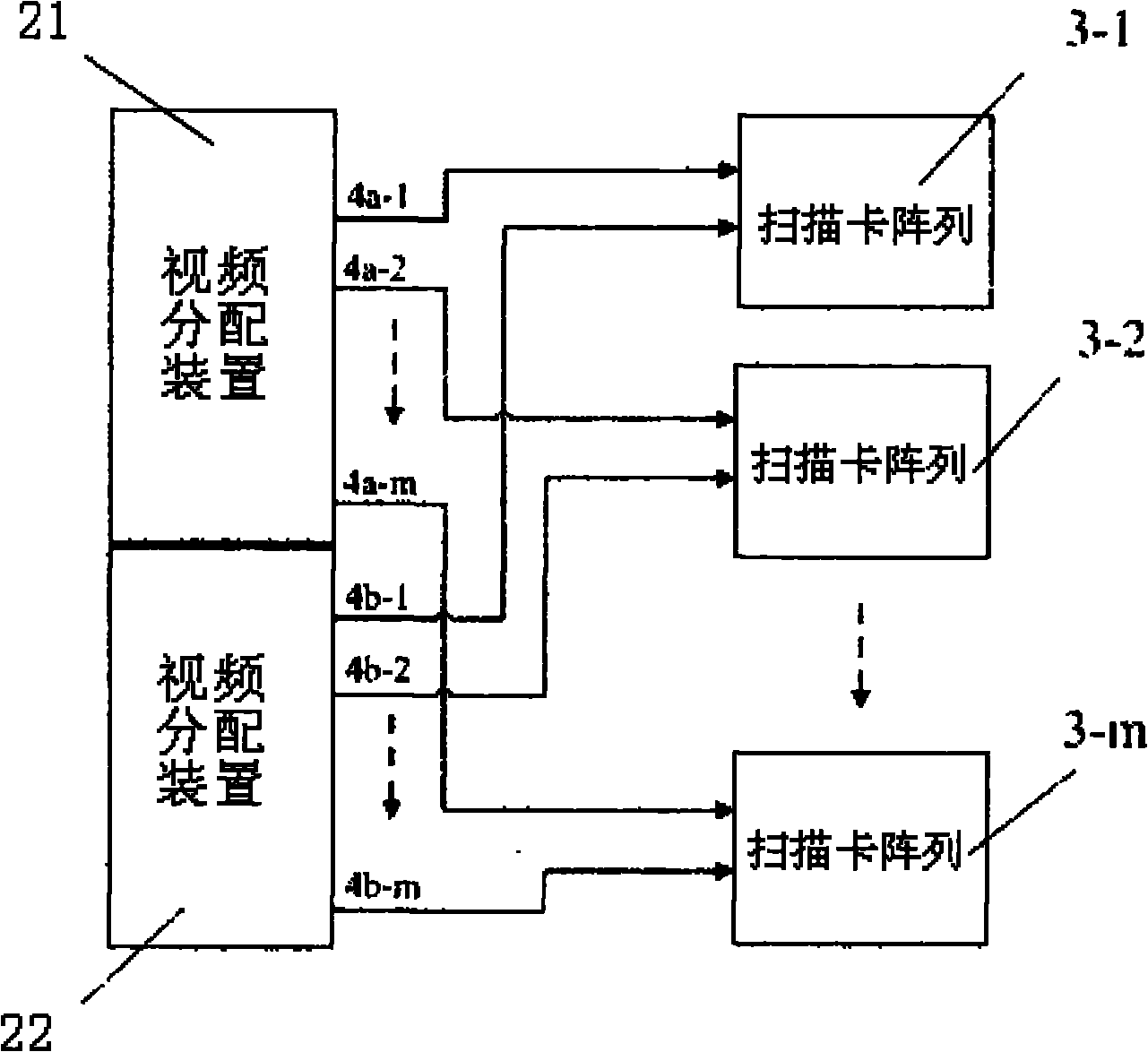
[0051] LED display dual-computer hot backup system such as Figure 15 As shown, the video transmission device adopts optical fiber sending cards 211, 212, the video distribution device adopts optical fiber receiving distributors 221, 222, the output of the video distribution device adopts LVDS interface transmission, the transmission line adopts LVDS transmission line, and the connection between scanning cards also adopts LVDS Transmission line.

[0052] If it is necessary to control a display screen with 1024×768 pixels, and a single scanning card controls a cabinet with 128×64 pixels, then take m=768 / 64=12, n=1024 / 128=8, that is, the total control of the system 8×12 cabinets. When one vide...


PUM


Abstract

The invention relates to a dual computer hot-standby system of an LED display screen, which comprises two video distribution devices and m scanning card arrays. Each video distribution device is respectively connected with the m scanning card arrays, the received video data are decoded, accessed, recombined and packed and are respectively output to the m scanning card arrays through m paths of parallel interfaces; and each path of signals output by the video distribution devices is transmitted to n scanning cards forming the scanning card array, each scanning card intercepts data for setting regions of pixel points, and the data intercepted respectively are subjected to decoding, accessing, data processing and distribution and output to the LED display screen. By adopting two sets of separate data channels, the invention can realize heat switching of the system when some sets of data channels are in trouble, thereby the stability and the reliability of the system is improved and the ratio of manual maintenance is also greatly reduced.

Description

technical field [0001] The invention relates to a hot backup system for LED display screens, in particular to a dual-computer hot backup system for LED display screens. Background technique [0002] With the increasing popularity of LED display screens, people's requirements for LED display screens are becoming more and more stringent, among which the stability of LED display screen operation is the most important and basic requirement. No matter how gorgeous the display effect of the LED display is, once there are unstable factors in the control link, the image of the entire display will be greatly reduced in people's minds. Since the use environment and conditions of LED display screens are different, sometimes even very harsh, it is more necessary to improve the stability of LED display screen operation in a crucial position. [0003] The Chinese Invention Patent Bulletin discloses "A LED Video Control System" (publication date: April 16, 2008, announcement number: CN201...

Claims


Application Information

Patent Timeline
Patent Type & Authority Applications(China)
IPC IPC(8): G09G3/32H04N5/268
Inventor 丁铁夫王瑞光严飞李强
Owner CHANGCHUN CEDAR ELECTRONICS TECH CO LTD
Learn More