
High-tenacity and low-tension spinning device

A low-tension, high-strength technology, applied to spinning machines, continuous winding spinning machines, textiles and papermaking, etc., can solve the problem of increased yarn breakage, improved ring-spun yarn quality, and ring-spun yarn Problems such as strong and weak rings can be solved to achieve the effect of reducing spinning tension fluctuations, reducing phenomenon and fly, and improving the production environment

Active Publication Date: 2010-11-24
SHANGHAI TEXTILE GRP DETECTION STANDARD CO LTD
View PDF6 Cites 25 Cited by
  • Summary
  • Abstract
  • Description
  • Claims
  • Application Information

AI Technical Summary

Problems solved by technology

However, ramie spinning machines are mostly borrowed from wool spinning or cotton spinning ring spinning machines, and the characteristics of ramie fibers are thick fibers, high bending stiffness, and spinnability is far inferior to wool fibers and cotton fibers. do not adapt
[0009] (2) The problem of improving the quality level of ring spinning yarn
[0011] In addition, a large number of new high-speed looms are being popularized and applied at present, but due to the strong weak ring and hairiness of the ring-spun yarn, the number of yarn breakages of the loom increases under high-speed conditions, and the high-speed and high-yield purpose of the loom cannot be achieved.
[0012] (3) High-yield and energy-saving issues of ring spinning
[0018] (2) Defects of high spinning tension and tension fluctuation
However, due to the limitation of the structure of this false twister device, the strength of the yarn is 18% lower than that of the traditional ring spinning yarn, and the elongation is 15.6% lower than that of the traditional ring spinning yarn. High tension defects have not been fundamentally resolved

Method used


Image

  • High-tenacity and low-tension spinning device
  • High-tenacity and low-tension spinning device
  • High-tenacity and low-tension spinning device

Examples


Embodiment Construction

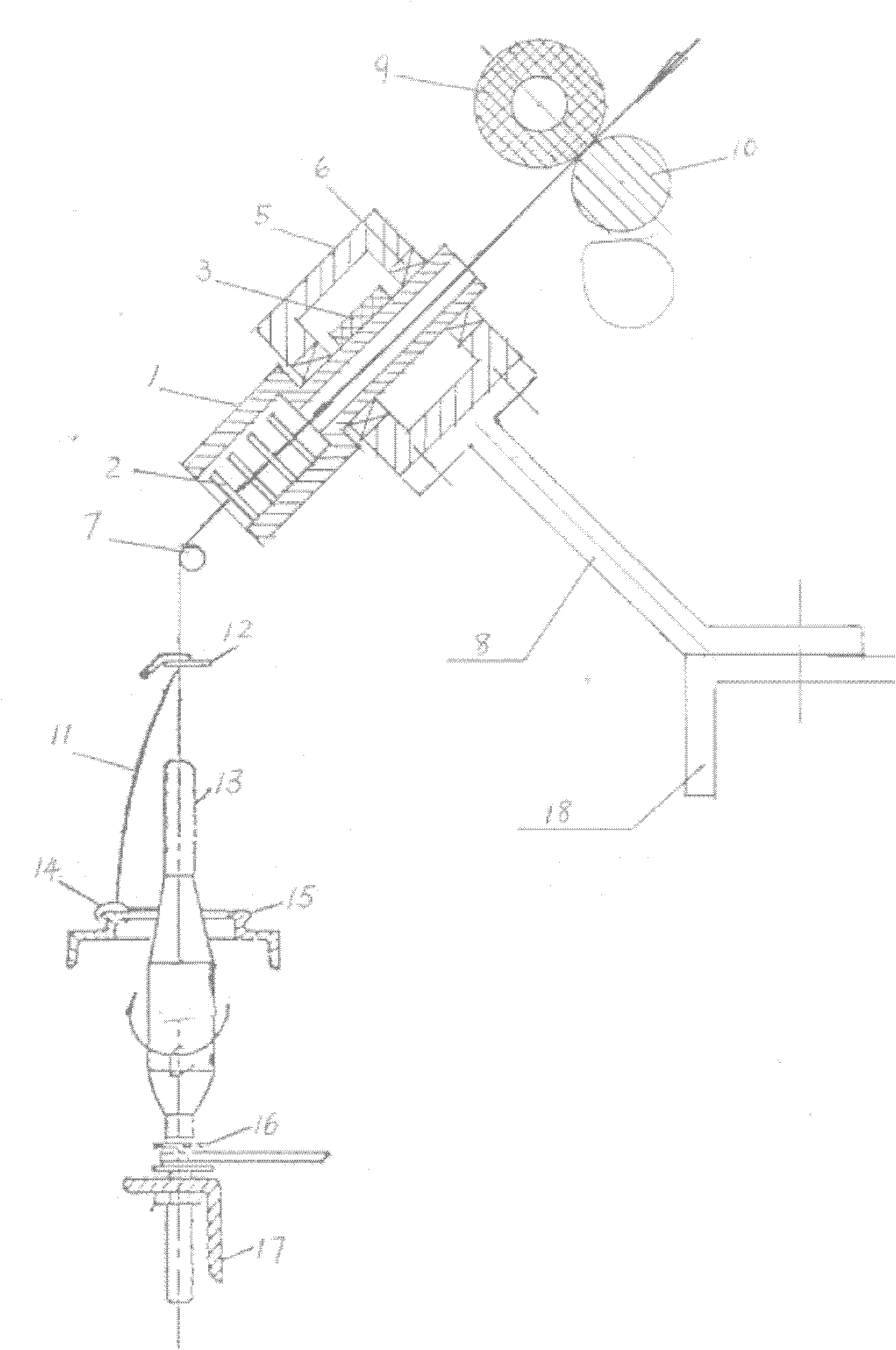
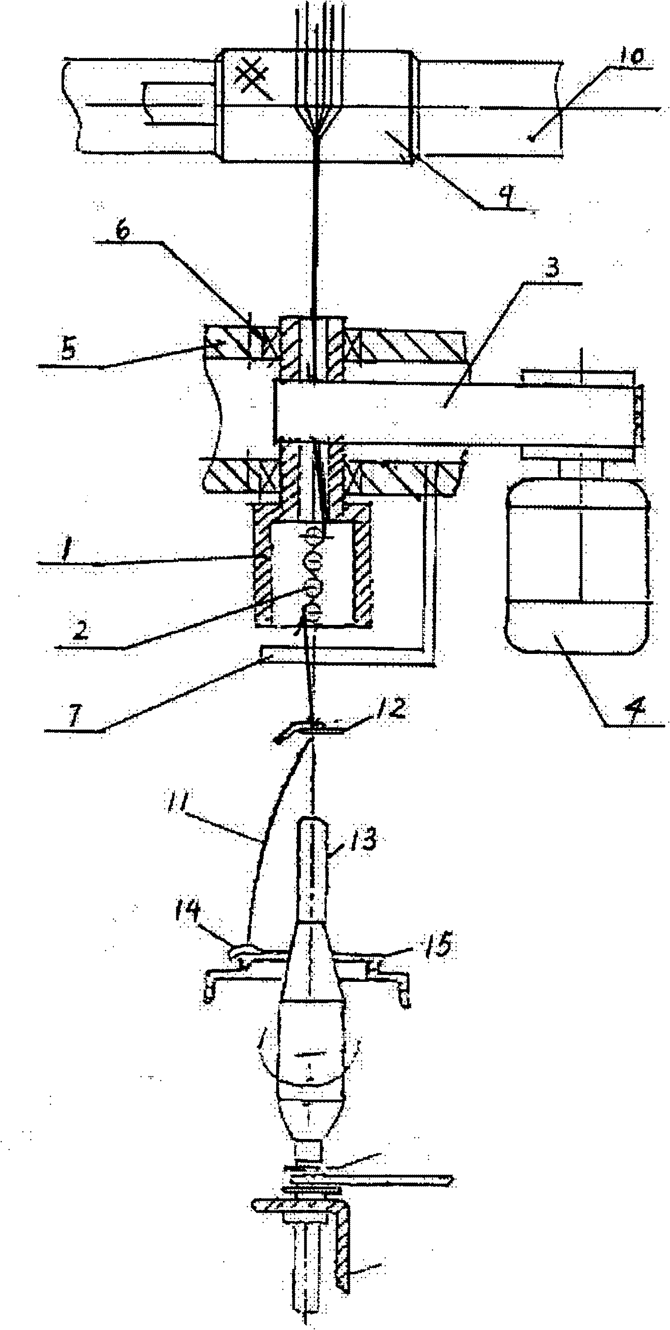
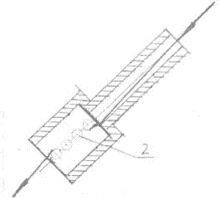
[0043] The frame member 5 arranged along the length direction of the ring spinning machine is fixed on the car panel 18 by the connector 8, the motor 4 is fixed on the car head, and the transmission belt 3 passes through the middle of the frame member 5 and cuts the axis of the false twister 1. to contact. The false twister 1 is fixed on the two frames of the frame member 5 through two bearings 6, and four tension damping needle bars 2 are provided.

[0044] During the production process, the roving fiber bundle output from the front nip composed of the front rubber roller 9 and the front roller 10 enters the false twister 1, and is wrapped around the tension damping needle bar 2 at the lower end of the false twister 1, and then output, through The yarn guide rod 7 and the yarn guide hook 12 are wound on the bobbin 13 afterward.

[0045] The tension damping needle bar 2 plays the following two functions:

[0046]One is to use its axial frictional resistance to the yarn 11 to...


PUM


Abstract

The invention relates to a high-tenacity and low-tension spinning device, which is used for ring spinners in textile industry. In the invention, a frame member is arranged along the length direction of a ring spinner in the middle of a spinning section between a front jaw and a yarn guide hook, a false twisting unit arranged corresponding to a spindle is fixed on the two borders of the frame member by two bearings and makes tangential transmission by a driving belt driven by a motor, and a yarn tension damping needle rod is arranged in the false twisting unit. By using the invention, the spinning tenacity is greatly improved, the spinning tension is reduced, and the spinning tension difference of large cop, middle cop and small cop is reduced, thereby realizing low-tension spinning; yarn filoplume is reduced, rubber roller is not wound by fibre frequently, and flyings are reduced, thereby improving spinning environment and spinning quality; heavy twist torsional moment is featured, the device can be applied to yarn with bigger hardness and cruder fibre, fibre material scope is enlarged, and raw material cost is reduced; and installation of the low-tension spinning device keeps the mechanism of the traditional ring spinners unchanged and is fit for modification of ring spinners for cotton / yarn / ramie / silk spinning.

Description

technical field [0001] The invention relates to the field of textile industry, in particular to a high-strength and low-tension spinning device used on a traditional ring spinning machine. Background technique [0002] The traditional ring spinning machine is the main type of spinning machine. The ring spinning technology is mature and the variety of yarns is widely adaptable. At present, about 60% of the total yarn production in the world is produced by the ring spinning machine. [0003] With the continuous expansion of the range of textile fiber raw materials and the improvement of yarn quality requirements, ring spinning technology is also facing problems that need to be solved urgently. [0004] 1. Problems faced by ring spinning technology: [0005] (1) Unsuitable for the ever-expanding range of fiber raw materials [0006] For example, sulfonamide fiber is an organic high-temperature-resistant fiber independently developed by Shanghai Textile Research Institute and ...

Claims


Application Information

Patent Timeline
IPC IPC(8): D01H1/02D01H1/11D01H5/28
Inventor 王林尧杨波戴自怡宋允林壁珍张振华方磊何锡辉华根大张德良
Owner SHANGHAI TEXTILE GRP DETECTION STANDARD CO LTD
Learn More