Nail gun aerosol can and filling method thereof

An aerosol can and nail gun technology, applied in packaging, nailing tools, dispensing devices, etc., can solve the problems of difficult to reliably seal the inner bag and the output valve, high loss of pressurized propelling gas, easy leakage, etc.

Active Publication Date: 2011-11-30
NANJING TENGYA PRECISE TECH DEV CO LTD
View PDF12 Cites 0 Cited by
  • Summary
  • Abstract
  • Description
  • Claims
  • Application Information

AI Technical Summary

Problems solved by technology

Practice has proved that this type of fuel dispenser has the following disadvantages: 1), first fill the external tank with pressurized propellant gas (usually a combustible gas with the same composition as the inner bag), and then fasten the tank cover with the external tank Sealing and fastening, pressurized propulsion gas loss is more, thereby increasing the cost, and causing pollution to the environment; 2), the inner bag and the output valve are difficult to seal reliably, and it is easy to cause leakage
Practice has proved that this assembly has the following disadvantages: 1), when filling, it is necessary to fill the external tank with pressurized propellant gas (usually a combustible gas with the same composition as the inner bag), and then connect the tank cover with the external tank. The tank is picked up and sealed tightly, so the pressurized propulsion gas is lost more, the cost is increased and the environment is polluted; 2), the sealing between the lower valve body and the upper valve body is not ideal, and it is easy to leak

Method used


Image

  • Nail gun aerosol can and filling method thereof
  • Nail gun aerosol can and filling method thereof
  • Nail gun aerosol can and filling method thereof

Examples


Embodiment 1

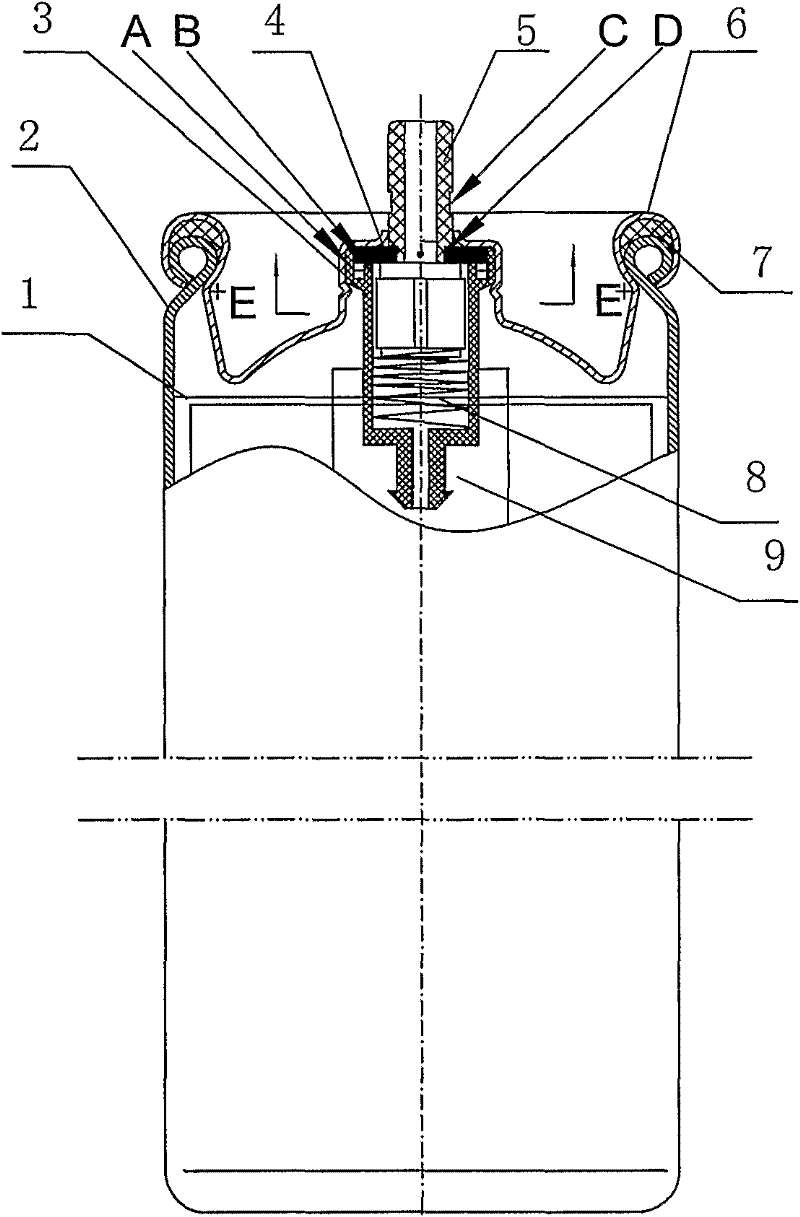
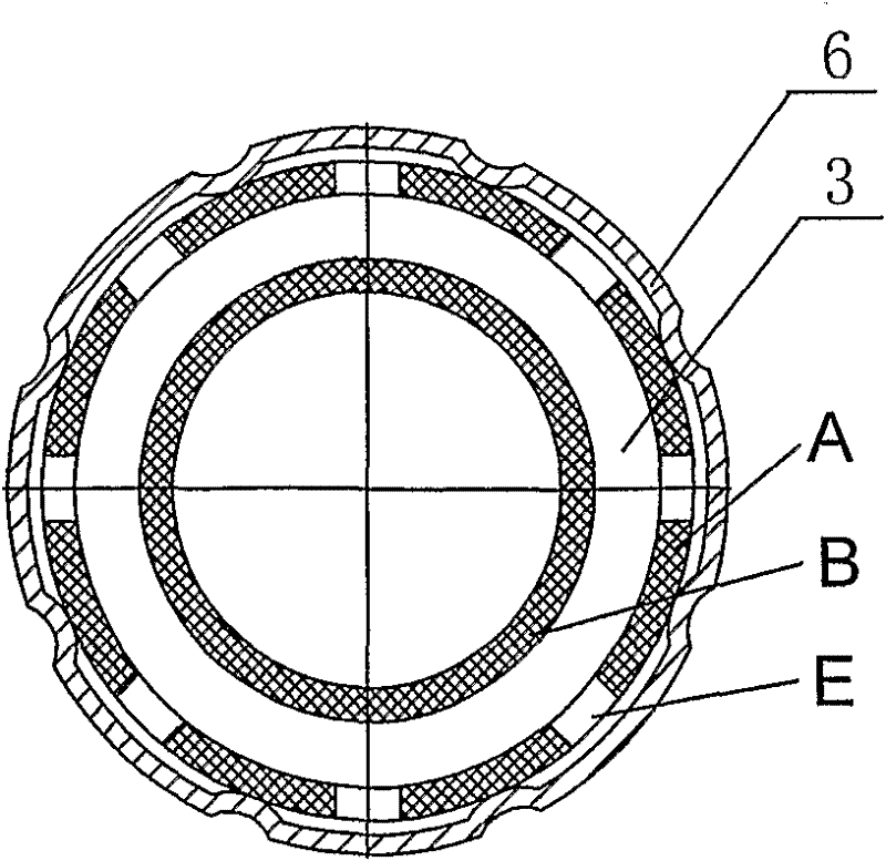
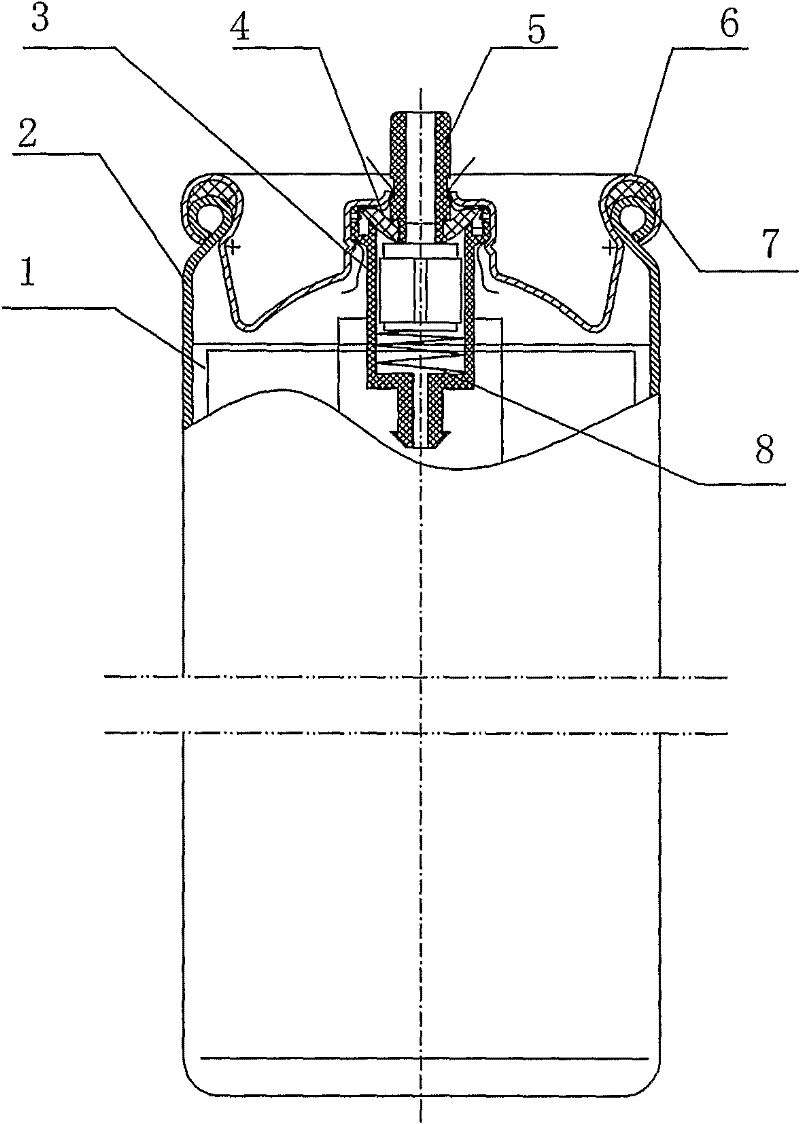
[0024] The nail gun aerosol can of the present embodiment is as figure 1 As shown, the tank body is composed of a tank cover 6 and a cylindrical tank cup 2 with flanged edges and a filling seal 7 snapped together. The middle part of the tank cover 6 extends outward to form a boss with a central opening. The opening in the center of the boss forms an outward seam, and the upper end of the fixed tubular valve body 3 is embedded in the boss, leaving an air gap between the two. The lower end of the valve body 3 is compressed and sealed with the lower part of the valve body, and the center is formed with an air outlet hole communicating with the inside of the inner bag 1, and the periphery is connected with the upper part of the inner bag 1 in the tank by hot-melt sealing. Installed in the valve body 3 is a valve core 5 that can be displaced up and down, thus having first, second and third axial positions. Elastic part 8 (spring) is housed between the lower end of spool 5 and valv...


PUM


Abstract

An aerosol container of the nail gun includes a container body, a valve body (3), a valve core (5), a sealing ring (4) and an elastic piece (8). The upper end of the valve body (3) is flush mounted in the container body. The lower end of the valve body (3) is in tight connection with an inner bag (1). The valve core (5) is installed in the valve body (3). The upper end of the valve core (5) forms a tubular valve nozzle. An inner circumference B and an outer circumference A are manufactured on the upper end of the valve body (3), and the inner circumference B is lower than the outer circumference A. The lower end face of the sealing ring (4) abuts against the upper end of the inner circumference B, and the margin of the sealing ring (4) is contained in the outer circumference A. When the valve core (5) is in the first axial position, the upper necking section C and the lower necking section D is respectively located inside and out side of said boss, and the upper surface and the lower surface of the sealing ring (4) respectively abut closely to the boss and the inner circumference B; when the valve core (5) is in the second axial position, the upper necking section C locates on the opening of the boss, and the upper surface of the sealing ring (4) departs from the lower surface of the boss. Therefore, it's convenient to fill, and it's effective to prevent gas leakage.

Description

technical field [0001] The invention relates to an improvement of a fuel container for providing fuel to a fastener power driving tool, in particular to an aerosol tank for a nail gun, and also relates to a filling method thereof. Background technique [0002] Tools (such as nail guns) that drive fasteners by means of combustion power are widely used in many fields such as architectural decoration. Retrieval found that US patents Re32,452; US4,403,722, US4,483473; US4,483474; US5,197,646 and US5,263,439 respectively carried out related descriptions. [0003] When the above-mentioned combustion power-driven fastener tool is used, a fuel container containing fuel is required to provide fuel as a working medium to the combustion chamber of the tool through an output valve. US Patent No. 5,115,944 promptly discloses the typical structure of this type of fuel dispenser: it includes an outer tank, an inner bag, an output valve, and a tank cover. The injection valve is engaged in...

Claims


Application Information

Patent Timeline
Patent Type & Authority Patents(China)
IPC IPC(8): B65D83/14B65D83/44B25C1/08
CPCB65D83/425B25C1/08
Inventor 陈宇红
Owner NANJING TENGYA PRECISE TECH DEV CO LTD
Why Eureka
Try Eureka