
High-precision joining method of uneven surface object picture

A technology with uneven surface and high precision, applied in image data processing, instruments, calculations, etc., can solve problems such as stitching errors, and achieve the effect of eliminating stitching errors and improving stitching accuracy.

Inactive Publication Date: 2011-12-21
ZHEJIANG UNIV
View PDF0 Cites 0 Cited by
  • Summary
  • Abstract
  • Description
  • Claims
  • Application Information

AI Technical Summary

Problems solved by technology

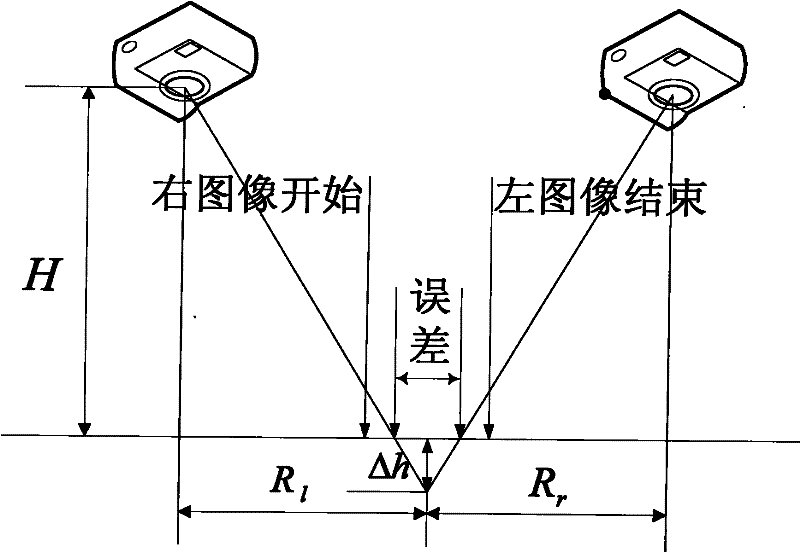
[0011] from figure 1 It can be seen that since the camera imaging complies with perspective projection (because there is no lens with infinite focal length), the degree of unevenness of the object surface Δh will bring stitching errors

Method used


Image

  • High-precision joining method of uneven surface object picture
  • High-precision joining method of uneven surface object picture
  • High-precision joining method of uneven surface object picture

Examples


Embodiment Construction

[0064] A specific implementation of the present invention will be described in detail below with reference to examples.

[0065] (1) According to the overlapping area in the first image and the second image that need to be spliced, the structured light three-dimensional scanner is used to obtain the five-tuple (x w , Y w ,z w , U r , V r );

[0066] The first image and the second image here are obtained by photographing surface concave-convex objects, and have a partial overlap area. During three-dimensional scanning, it is required to cover at least the part of the surface concave-convex object corresponding to the overlap area to facilitate error correction.

[0067] In the five-tuple, (x w , Y w ,z w ) Is the coordinate of the sampling point in the three-dimensional space (world coordinate system), (u r , V r ) Is the coordinate of the sampling point in the first image;.

[0068] (2) Fitting of the best reprojection plane based on the least square method

[0069] Assuming that the be...


PUM


Abstract

The invention discloses a high-precision joining method of an uneven surface object picture. A coordinate in a world coordinate system of a plurality of sampling points on an uneven surface object is obtained by utilizing three-dimensional scanning according to an overlapped area of a first image and a second image to be joined, the coordinate is fitted in a least square method to obtain a best re-projection plane, and a best re-projection coordinate system is established; the coordinate of each sampling point in the world coordinate system is converted to a coordinate in the best re-projection coordinate system, and an error between an ideal image coordinate and a real image coordinate of the sampling point is calculated according to the internal and the external parameters of a camera; the error between the ideal image coordinate and the real image coordinate of all pixels in the overlapped area is obtained through interpolation; the first and the second images are corrected so as to obtain and to join the first image and the second image with no error. Pin-hole model simulates imaging of infinite focal-length lens, which is followed by the imaging of the camera, so the generated picture eliminates the joining error caused by the uneven surface perspective projection.

Description

Technical field [0001] The invention relates to the field of computer digital image processing, in particular to a high-precision splicing method for photographs of surface concave and convex objects. The depth information obtained by three-dimensional scanning is used to eliminate the affine of the concave and convex surface caused by perspective projection of such ordinary camera photos. Corresponding error. Background technique [0002] The current image registration algorithms are based on the assumption that (u, v) and (U, V) are respectively the image points (corresponding points) of the same object point in different images, and the following implicit functions are generally considered relationship [0003] F(u, v, U, V) = 0 (1) [0004] Note: The function F in the above formula is a vector function, which can be written as the following component form: [0005] f ( u , v , U , V ) = 0 g ( u , v , U , V ) = 0 ...

Claims


Application Information

Patent Timeline
Patent Type & Authority Patents(China)
IPC IPC(8): G06T5/50
Inventor 石洗凡刁常宇鲁东明
Owner ZHEJIANG UNIV
Learn More