
Position identifying system and detection method of multi-layer linear array laser spot

A linear array laser and identification system technology, applied in the direction of using optical devices, measuring devices, instruments, etc., can solve the problems of high staff requirements, difficult adjustment, high labor intensity, etc., to achieve the simplified circuit system, easy repair and maintenance , the effect of increasing redundancy

Active Publication Date: 2010-11-10
CHINA UNIV OF MINING & TECH (BEIJING) +1
View PDF3 Cites 16 Cited by
  • Summary
  • Abstract
  • Description
  • Claims
  • Application Information

AI Technical Summary

Problems solved by technology

[0007] The main purpose of the present invention is to overcome the shortcomings of the existing measurement and positioning technology, such as difficulty in adjustment, high requirements for staff, and high cost. Moreover, due to the precision of the instrument, it is easily affected by harsh environments, and the specific implementation is quite difficult. For difficult defects, a new multi-layer linear array laser spot position recognition system and detection method is provided, which uses laser as the propagation medium, uses optics, electronics and computer knowledge to perform non-contact measurement and positioning, and overcomes the limitations of traditional measurement and positioning methods Due to the limitations of high labor intensity, long working hours and great influence on the working environment, it opens up wider and more special application environments and fields for measurement and positioning technology

Method used


Image

  • Position identifying system and detection method of multi-layer linear array laser spot
  • Position identifying system and detection method of multi-layer linear array laser spot
  • Position identifying system and detection method of multi-layer linear array laser spot

Examples


Embodiment 1

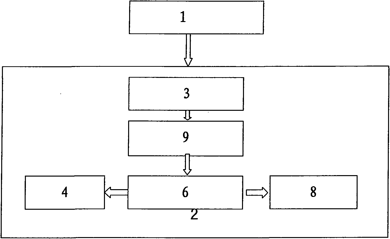
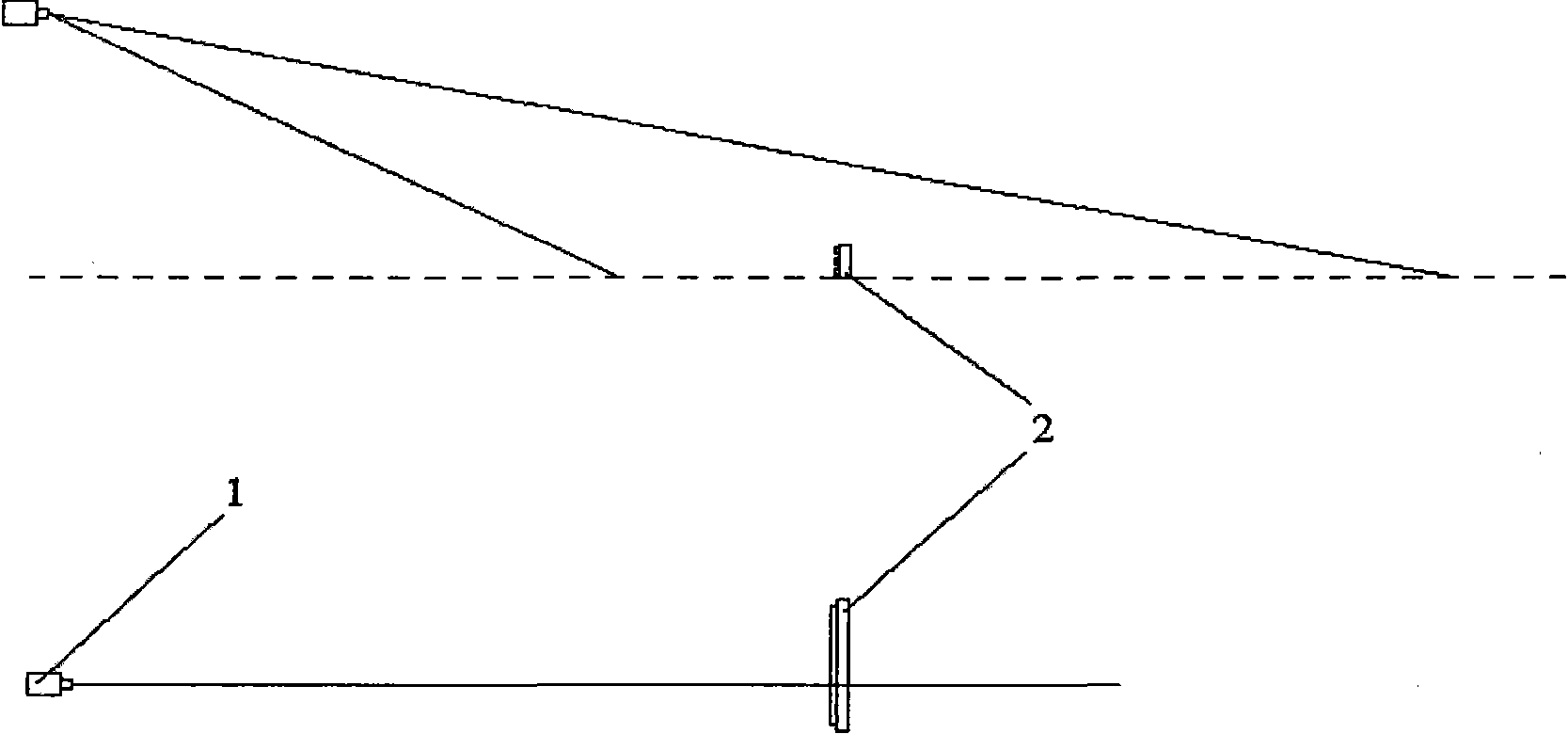
[0058] The multi-layer linear array laser spot position recognition system and detection method of the preferred first embodiment of the present invention, such as figure 1 , figure 2 , as shown in FIG. 3 , consists of a line laser transmitter 1 and a detection device 2 , wherein the detection device includes a laser detector 3 , a follow-up circuit 9 , a single-chip microcomputer 6 , a display 4 , an output interface 8 and a power supply 7 . The system uses laser detection and recognition technology to establish a position correspondence relationship with the line laser emitter by identifying the position of the laser spot, and can realize the one-dimensional position recognition of long-distance objects using laser as the medium.

[0059] Such as Figure 1-2 As shown, the line laser transmitter 1 emits a fan-shaped laser beam, and the fan-shaped laser beam can be designed and manufactured according to needs. What the fan-shaped laser beam shines on the object is a linear s...

Embodiment 2

[0077] refer to Figure 3BAs shown, the multi-layer linear array laser spot position recognition system and detection method of the preferred second embodiment of the present invention use a line laser emitter 1 and two detection devices 2 in combination, and other structures and detection methods are the same as in Embodiment 1 .


PUM


Abstract

The invention relates to a position identifying system and a detection method of a multi-layer linear array laser spot. The position identifying system comprises a linear laser transmitter and a detection device, wherein the detection device comprises laser detectors, subsequent circuits, a single-chip machine, a display, an output interface and a power supply. According to the requirements of precision and length, a certain quantity of laser detectors are uniformly arranged and installed at certain intervals to form a linear array as one layer, multiple layers are made in parallel and then are used as one block, and multiple blocks are spliced to form the detection device. The linear laser transmitter forming a required certain position relation with the detection device transmits fan-shaped laser beams, the laser detectors induce the fan-shaped laser beams and generate electric signals which are processed and calculated by the subsequent circuits and the single-chip machine so that the laser detector in the center of the spot can be identified, and the position of the spot in the arrangement direction of the laser detector is obtained. The position information data can be directly displayed on the display and also be outputted by an output interface for other kinds of equipment.

Description

technical field [0001] The invention relates to a position recognition system in the field of measurement and positioning, in particular to a multi-layer linear array laser spot position recognition system in the field of laser detection and recognition systems. Background technique [0002] Measurement and positioning technology is inseparable from human practical activities, and it is also constantly developing and changing with the progress of society. [0003] Since the 1950s, measurement and positioning technology has begun to develop in the direction of electronization and automation. With the emergence of various light sources such as lasers and infrared light, the physical distance measurement technology has also developed rapidly, and there have been light wave range finders with lasers, infrared light and other light sources as carriers and microwave distance measurers with microwaves as carrier waves. The appearance of the rangefinder, the electromagnetic wave ra...

Claims


Application Information

Patent Timeline
Patent Type & Authority Applications(China)
IPC IPC(8): G01B11/00
Inventor 吴淼刘建功李睿朱信平田劼魏景生张兰胜李树辉薛光辉高娟王苏彧穆晶高峰杜毅博郝明锐张伟杰杨阳岳素青
Owner CHINA UNIV OF MINING & TECH (BEIJING)
Learn More