
Flue gas dedusting energy-saving device for boiler

A technology for boiler flue gas and energy-saving devices, which is applied in the directions of climate sustainability, greenhouse gas reduction, and fixed duct components. temperature and other issues, to achieve the effect of easy maintenance and ash cleaning, saving boiler room space, and reducing exhaust gas temperature

Active Publication Date: 2012-09-12
GUANGZHOU DEVOTION THERMAL TECH
View PDF1 Cites 0 Cited by
  • Summary
  • Abstract
  • Description
  • Claims
  • Application Information

AI Technical Summary

Problems solved by technology

However, it can be seen from the above that the layout of the components of the above-mentioned patent is not compact enough, and the heat exchange unit and the dust removal unit are not integrated, resulting in a large space occupation; in addition, the design of the heat exchange unit is too simple, and it is difficult to fully reduce the smoke exhaust. temperature, increase boiler efficiency

Method used


Image

  • Flue gas dedusting energy-saving device for boiler
  • Flue gas dedusting energy-saving device for boiler

Examples


Embodiment 1

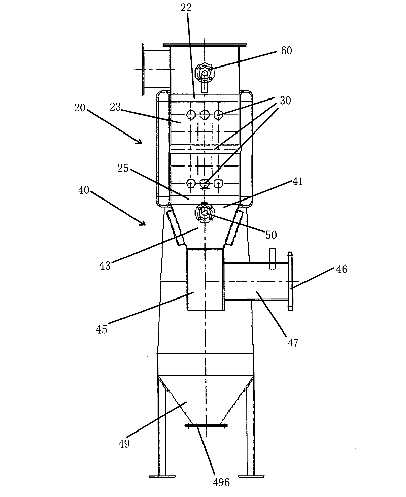
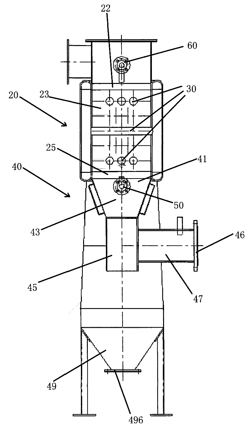
[0017] Please refer to FIG. 1 , the boiler flue gas dust removal and energy saving device of the present invention mainly includes two parts: a heat exchange unit 20 and a dust removal unit 40 .

[0018] The heat exchange unit 20 is provided with a high temperature flue gas inlet 22 , a low temperature flue gas outlet 25 and a heat exchange space 23 defined between the high temperature flue gas inlet 22 and the low temperature flue gas outlet 25 . Several heat exchange pipes 30 are arranged in the heat exchange space 23 , and a fluid (water in this embodiment) for exchanging heat with the flue gas circulates in the heat exchange pipes 30 .

[0019] According to the sequence from the high-temperature flue gas inlet 22 to the low-temperature flue gas outlet 25, the heat exchange pipes 30 are divided into five layers, and the heat exchange pipes 30 of each layer are respectively located in a plane parallel to the horizontal plane. Each layer includes three or more heat exchange p...

Embodiment 2

[0028] As another kind of scheme of the present invention, other parts are identical with embodiment 1, and difference is:

[0029] Another induced draft fan 60 is arranged in the high-temperature flue gas inlet 22 .

[0030] The heat exchange pipes 30 are divided into eight layers, and each layer includes six heat exchange pipes 30 . The orientation of the heat exchange tubes 30 in different layers can be rotated by 60 degrees relative to the orientation of the heat exchange tubes 30 in the adjacent layer.


PUM


Abstract

The invention discloses a flue gas dedusting energy-saving device for a boiler, comprising a heat exchanging unit and a dedusting unit, wherein the heat exchanging unit is provided with a high-temperature flue gas inlet, a low-temperature flue gas outlet and a heat exchanging space arranged between the high-temperature flue gas inlet and the low-temperature flue gas outlet, a plurality of heat exchanging pipelines are distributed in the heat exchanging space, and fluid bodies for exchanging heat with flue gas circulate in the heat exchanging pipelines; the dedusting unit is provided with a dust flue gas inlet and a dustless flue gas outlet, and the dust flue gas inlet is directly communicated with the low-temperature flue gas outlet of the heat exchanging unit. The heat exchanging pipelines are divided into at least two layers, three or more heat exchanging pipelines are provided in each layer, wherein the moving direction of the heat exchanging pipelines in different layers rotate for an angle of 30-60 DEG relative to the moving direction of the heat exchanging pipelines in the adjacent layer according to the sequence from the high-temperature flue gas inlet and the low-temperature flue gas outlet, and the heat exchanging pipelines located in the same layer are mutually paralleled. The energy-saving device of the invention integrates lowering flue gas discharging temperature and reducing discharge of dust in flue gas into a whole, has compact structural arrangement, and effectively saves the space of a boiler room.

Description

technical field [0001] The invention relates to an energy-saving device, in particular to a device for removing dust from boiler flue gas and recovering waste heat of the flue gas. Background technique [0002] At present, the exhaust gas temperature of a large number of boilers is very high. If the flue gas is directly discharged into the atmosphere, it will not only waste a lot of energy, but also cause thermal pollution to the surrounding environment, so it is necessary to recycle the waste heat of the flue gas. [0003] As disclosed in Chinese Patent No. 95201022.4, a flue gas purification and energy-saving device includes a smoke box, a half partition and an air-gas heat exchange element in the upper half of the smoke box, an air intake pipe in the upper left part of the smoke box, and an air intake pipe in the upper right part of the smoke box. There is an exhaust pipe, and there is a gas-solid separation element at the lower left of the smoke box, and an ash collecti...

Claims


Application Information

Patent Timeline
Patent Type & Authority Patents(China)
IPC IPC(8): F23J15/00F23J15/06F22D1/00B01D45/02F28D1/04F28F13/00
CPCY02E20/30
Inventor 常厚春李祖芹马革耿生斌尹显录张湘波
Owner GUANGZHOU DEVOTION THERMAL TECH
Learn More