
Radial-axial rolling bearing

A rolling bearing, axial technology, applied in the direction of rolling contact bearing, shaft and bearing, roller bearing, etc., can solve the problem that the radial-axial-rolling bearing is not suitable for high speed, the axial cylindrical roller is not enough to guide, Cylindrical rolling elements are prone to overlap and other problems, so as to achieve reliable guidance, improve sliding characteristics, and prevent overlapping.

Active Publication Date: 2010-11-03
SCHAEFFLER TECH AG & CO KG
View PDF1 Cites 13 Cited by
  • Summary
  • Abstract
  • Description
  • Claims
  • Application Information

AI Technical Summary

Problems solved by technology

[0003] The disadvantage here is that the cylindrical rolling bodies of the two axial bearings are not guided or not sufficiently guided by the individual retaining ring segments, so that the cylindrical rolling bodies tend to overlap, especially at higher rotational speeds
Radial-axial-rolling bearings of this type with a single retainer segment are not suitable for higher speeds especially due to insufficient guidance of the axial cylindrical rollers
Such individual retainer segments are unstable and tend to occupy unequal spacing from each other circumferentially at higher speeds
A further disadvantage is that such generic bearing systems can only be assembled at increased costs, since each individual rolling element of the axial bearing arranged on both sides must be connected to a retaining ring segment and must be assembled individually

Method used


Image

  • Radial-axial rolling bearing
  • Radial-axial rolling bearing
  • Radial-axial rolling bearing

Examples


Embodiment Construction

[0032] exist Figure 5 The radial-axial-rolling bearing shown in and marked with 1 consists of an inner ring 2 and an outer ring 3 arranged concentrically, the inner ring 2 and the outer ring 3 are kept at a distance from each other by a gap 4, wherein the outer ring 3 is provided with At least one fixing hole 5 runs through. The inner ring 2 is provided with recesses 6 for receiving cylindrical rolling bodies 7 which absorb radial forces and are guided in a retaining ring 8 . The rolling bodies 7 roll on running rails, not shown in detail, which are provided on the one side by the bottom of the recess 6 and on the other side by the inner shell surface of the outer ring 3 . In the axial direction, the rolling bodies 7 are securely guided by the likewise unmarked edges of the recesses 6 and are kept at a distance from one another in the circumferential direction by the retaining ring 8 .

[0033] In addition, the two thrust washers 9 and 10 also belong to the bearing system, ...


PUM


Abstract

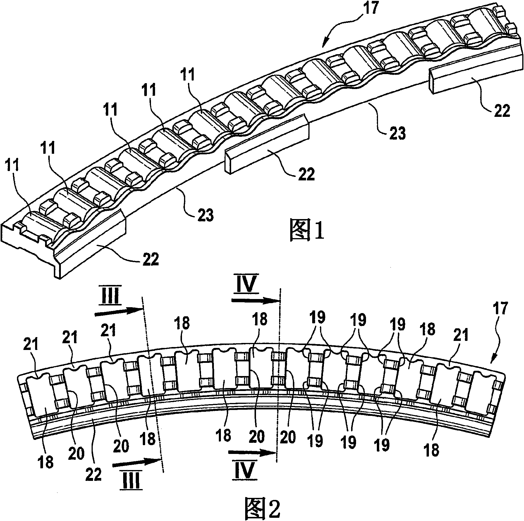
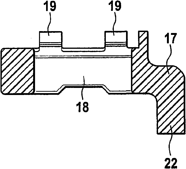
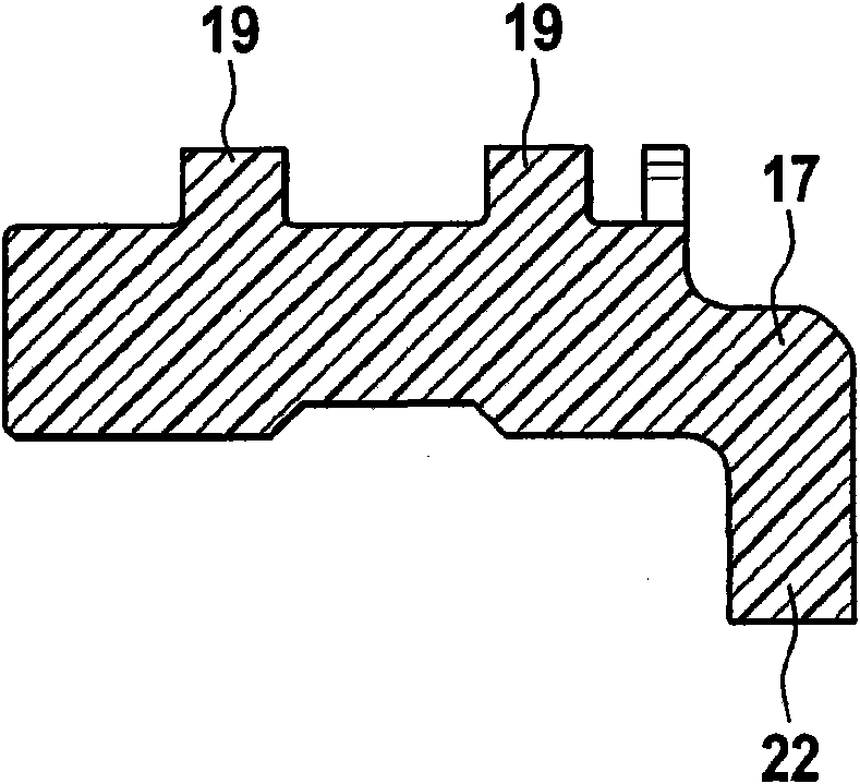
The invention relates to a radial-axial rolling bearing (1, 24) with an inner ring (2), to which an outer ring (3) is arranged coaxially, between which cylindrical rolling bodies (6) roll in order to absorb radial forces, and with cylindrical rolling bodies (11) arranged on both sides in order to absorb axial forces, the tracks of said rolling bodies being formed on the one hand by faces of the outer ring (3) and on the other hand by a washer disk (9, 10) each, wherein the cylindrical rolling bodies (11) are guided in cage segments, the guide bars of which engage in a gap (4) formed by the inner ring (2) and outer ring (3). Said bearing arrangement (1, 24) is characterized in that the cage segments (17, 25) are configured in an arched manner and have L-shaped angled guide bars (22) which extend over at least part of a peripheral expansion of the cage segments (17, 25) and each individual cage segment (17, 25) has a plurality of pockets (18) in each of which a cylindrical rolling body (11) is captively received. Due to this type of configuration of the cage segments (17, 25) the cylindrical rolling bodies (11) housed therein are guided on the associated tracks securely and precisely.

Description

technical field [0001] The invention relates to a radial-axial rolling bearing having an inner ring, coaxially arranged with an outer ring, in which cylindrical rolling bodies are arranged to absorb radial forces Rolling between the outer ring and the outer ring; and the radial-axial rolling bearing has cylindrical rolling elements arranged on both sides to receive axial force, and the running track of the cylindrical rolling element arranged to receive axial force is in Formed on one side by the end face of the outer ring and on the other side by a thrust washer in each case, wherein the cylindrical rolling bodies are guided in retaining ring segments whose guide webs engage In the gap formed by the inner and outer rings. Background technique [0002] Such a generically designed radial-axial rolling bearing is previously known from DE 36 20 102 A1. as by figure 1 As can be seen from the accompanying description, this type of bearing consists of an inner ring and an outer...

Claims


Application Information

Patent Timeline
Patent Type & Authority Applications(China)
IPC IPC(8): F16C9/00F16C19/30F16C33/46F16C33/48F16C33/50F16C19/54F16C33/51
CPCF16C19/30F16C33/4635F16C2300/14F16C33/513F16C33/48F16C19/381F16C33/4605F16C2322/39
Inventor 格哈德·纳根加斯特
Owner SCHAEFFLER TECH AG & CO KG
Learn More