
Backlight module

A backlight module and backplane technology, applied in optics, electric light source, nonlinear optics, etc., can solve the problems of low reflectivity of light source reflector 15, high cost of light source reflector 15, dark part of backlight module 10, etc., to achieve Improve uniformity, improve overall luminance, and reduce production costs

Inactive Publication Date: 2011-12-14
CORETRONIC (SUZHOU) CO LTD
View PDF0 Cites 2 Cited by
  • Summary
  • Abstract
  • Description
  • Claims
  • Application Information

AI Technical Summary

Problems solved by technology

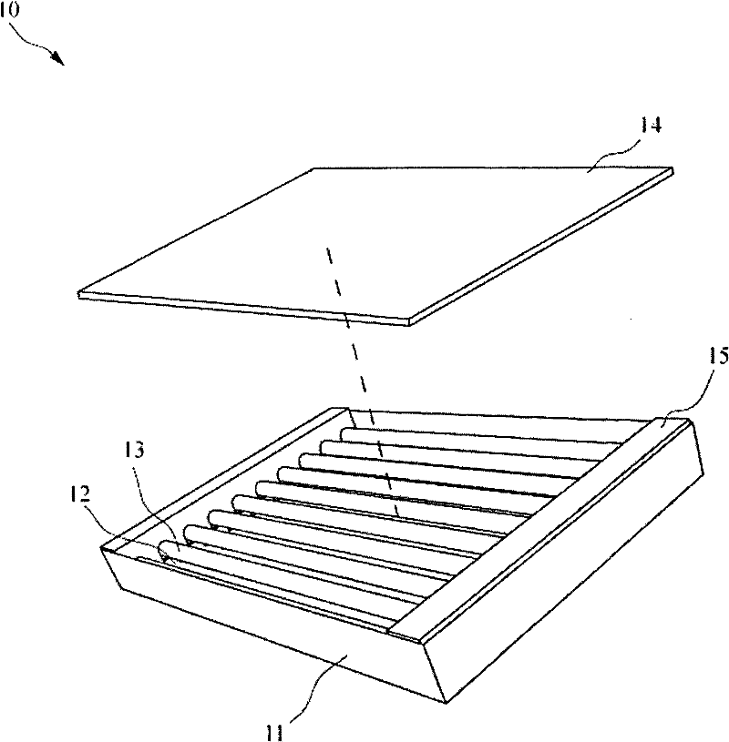
[0005] Since the light source reflector 15 is made by plastic injection process, the cost of the mold is relatively high, which makes the cost of the light source reflector 15 relatively high.
In addition, the material of the light source reflector 15 is plastic, and since the reflectivity of the plastic is low, the reflectivity of the light source reflector 15 is low, which may easily cause dark parts to appear on both sides of the backlight module 10.

Method used


Image

  • Backlight module
  • Backlight module
  • Backlight module

Examples


Embodiment Construction

[0063] The foregoing and other technical contents, features and effects of the present invention will be clearly presented in the following detailed description of a preferred embodiment with reference to the accompanying drawings. The directional terms mentioned in the following embodiments, such as: up, down, left, right, front or back, etc., are only referring to the directions of the drawings. Accordingly, the directional terms are used to illustrate and not to limit the invention.

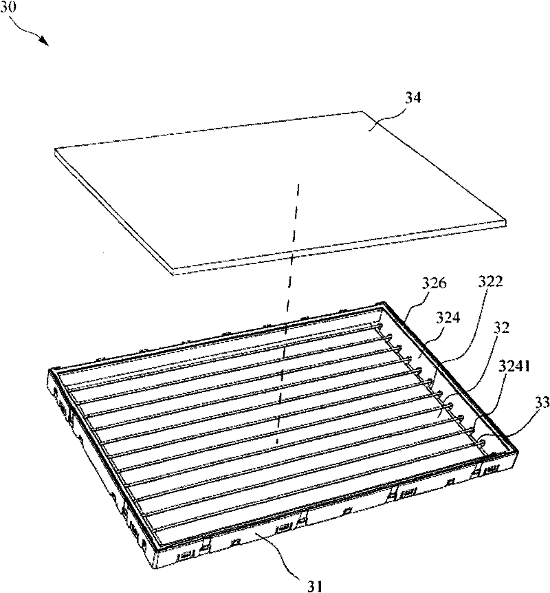
[0064] image 3 It is a three-dimensional schematic diagram of a backlight module according to an embodiment of the present invention. Figure 4 It is a schematic cross-sectional view of a backlight module according to an embodiment of the present invention. Please refer to image 3 and Figure 4 , the backlight module 30 in this embodiment belongs to the direct type backlight module, and the backlight module 30 includes a backplane 31 , a reflective structure 32 , a light source 33 and an o...


PUM

PropertyMeasurementUnit
reflectanceaaaaaaaaaa

Abstract

The invention relates to a backlight module comprising a back plate, a reflection structure and a light source, wherein one side of the back plate is provided with a U-shaped accommodating part; the U-shaped accommodating part comprises a bottom, a side part which is connected with the bottom and forms an angle with the bottom and a top connected with the side part and opposite to the bottom. The reflection structure is configured on the bottom and the top and forms an accommodating space together with the side of the back plate. The light source is configured on the back light and extends into the accommodating space.

Description

【Technical field】 [0001] The present invention relates to a backlight module, and in particular to a direct type backlight module. 【Background technique】 [0002] With the development of the industry, products such as mobile phones, digital cameras, digital video cameras, notebook computers, desktop computers, and televisions are all oriented towards more convenient and versatile products. Development in a functional and aesthetic direction. However, when using the above-mentioned products, the display screen is an indispensable human-machine communication interface, and the display screen of the above-mentioned product will bring more convenience to the user's operation. Currently, a liquid crystal display is a common display screen. However, since the liquid crystal display itself does not have the function of emitting light, a backlight module needs to be provided in the liquid crystal display as a light source to achieve the display function. [0003] figure 1 It is a...

Claims


Application Information

Patent Timeline
Patent Type & Authority Patents(China)
IPC IPC(8): G02F1/13357F21S8/00F21V21/00F21V7/04F21V5/00
Inventor 郝吉
Owner CORETRONIC (SUZHOU) CO LTD
Learn More