
High-efficiency foam destroyer adopting metal base composite PTFE (Polytetrafluoroethylene)

A technology of metal matrix composite and PTFE, which is applied in the direction of foam dispersion/prevention, chemical instruments and methods, filtration and separation, etc. It can solve the problem of low smoothness of metal material surface, increased difficulty of maintenance and cleaning of demister, and ineffective collection of thick monofilaments And other problems, to achieve high strength, improve service life, enhance the effect of strength

Inactive Publication Date: 2010-10-27
SHANGHAI METAL WIRE MESH PROD
View PDF3 Cites 14 Cited by
  • Summary
  • Abstract
  • Description
  • Claims
  • Application Information

AI Technical Summary

Problems solved by technology

However, in the face of fine mist droplets, the traditional wire mesh demister cannot be effectively collected due to the relatively thick monofilament, and due to the low smoothness of the surface of the metal material, it is easy to accumulate impurities and other reasons, making the maintenance and cleaning of the demister difficult. Increased difficulty

Method used


Image

  • High-efficiency foam destroyer adopting metal base composite PTFE (Polytetrafluoroethylene)
  • High-efficiency foam destroyer adopting metal base composite PTFE (Polytetrafluoroethylene)
  • High-efficiency foam destroyer adopting metal base composite PTFE (Polytetrafluoroethylene)

Examples


Embodiment 1

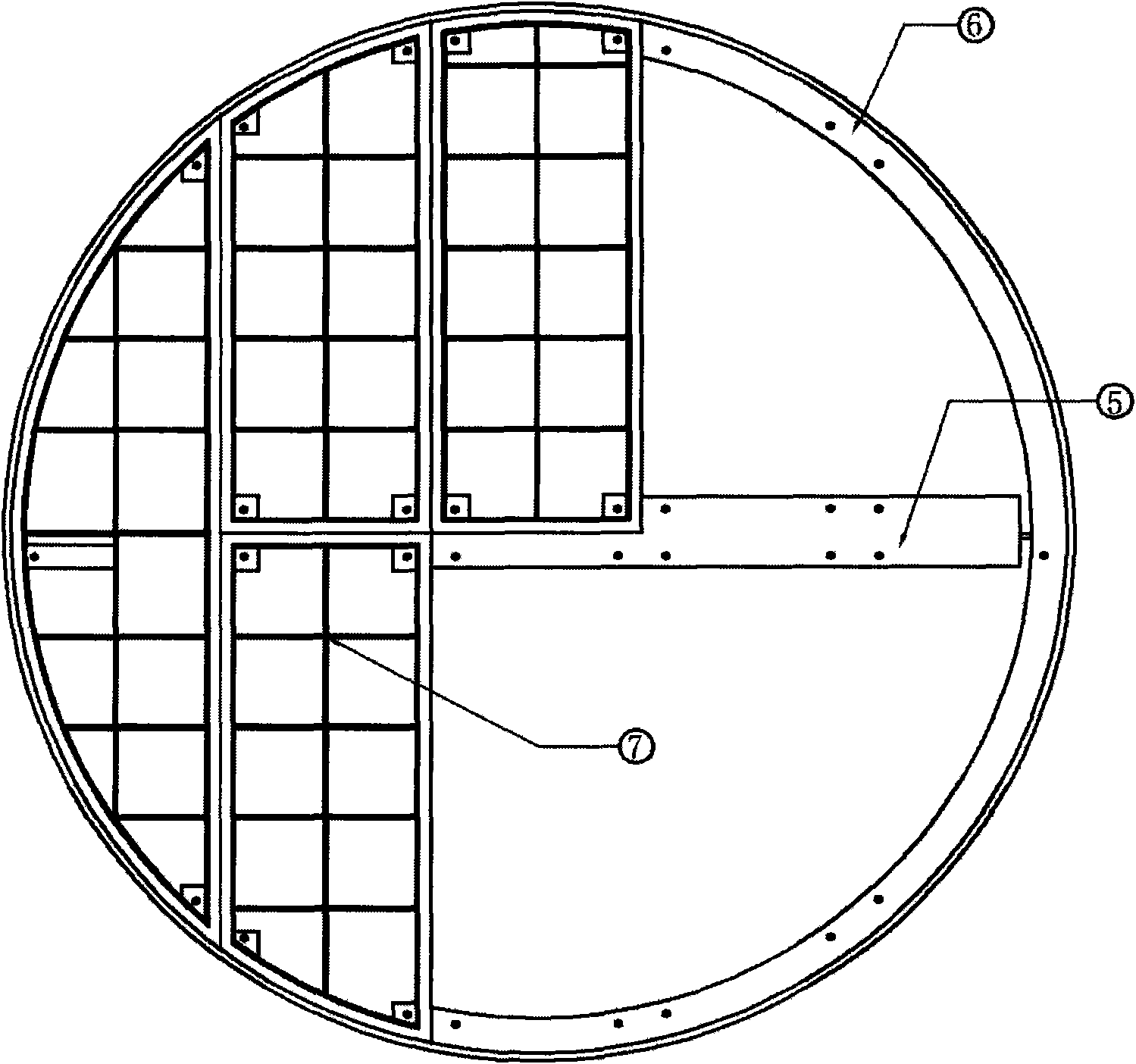
[0025] exist figure 1 Among them, the mesh block composed of metal-based composite PTFE separation mesh is clamped by the upper and lower grids and hoisted under the beam with bolts.

[0026] exist figure 2 , it shows that the bolt holes for hoisting are reserved at the corresponding positions of the support ring, and there are hoisting bolts at the four corners of the mesh block composed of each separated mesh.

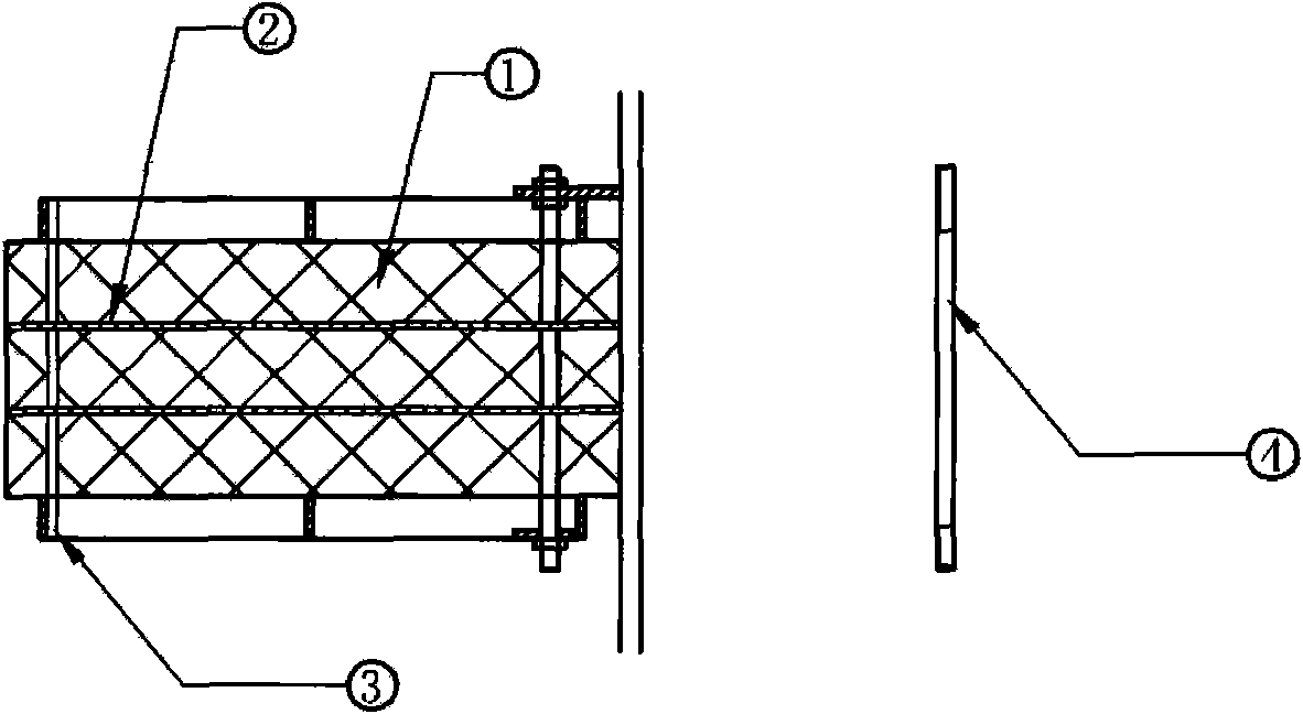
[0027] exist image 3 , shows the composition of each metal-based composite PTFE separation mesh block, which is composed of metal-based composite PTFE separation mesh, layered PTFE porous grid plate and bolt-fixed composite metal grid, in which the layered PTFE porous grid The plate divides the metal-based composite PTFE separation net into equal parts, and the number is determined by the height of the separation net that is actually required.

Embodiment 2

[0029] The manufacture method of described metal matrix composite PTFE separation net is as follows:

[0030] First, add 10% liquid extrusion aid isoparaffin to the PTFE powder, disperse evenly, let stand at a temperature of 40°C for 20 hours, extrude into a rod, pass through a combined roll machine at 60°C, and roll it into a film. Keep a certain speed and release the extrusion aid at a high temperature of about 260°C, prolong the cooling and setting time in the cooling setting furnace, keep at 60°C, add a separating agent to make PTFE start to separate out fibers; during the cooling process, add a certain proportion of water-dispersed PTFE, Composite the fiber into the stainless steel wire; then put the compounded material into the special oil-free self-lubricating multi-head special equipment to make a separation mesh, and add it between the separation mesh with a certain number of layers (generally 10-15 layers). The layered PTFE porous grid plate increases the collision o...


PUM


Abstract

The invention discloses a high-efficiency foam destroyer adopting metal matrix composite PTFE (Polytetrafluoroethylene). The integral foam destroyer mainly comprises a metal base composite PTFE separate mesh, a layered PTFE porous grid plate and a bolt fixing combination metal grid, wherein the metal base composite PTFE separate mesh is made from metal base composite PTFE material with is compounded with metal wires in the fibering process of PTFE. As a critical component in a chemical tower, the foam destroyer is a high-efficiency gas-liquid separation device and can be widely used in a chemical industry, a petroleum industry, a pharmaceutical industry, a light industry, an environmental protection industry and the like, especially suitable for the gas-liquid separation of vinylamine / water; in addition the foam destroyer not only can filter larger foams suspended in airflows, but also can filter liquid sprays of 0.2-0.5 micrometer.

Description

technical field [0001] The invention relates to a high-efficiency demister using metal-based composite PTFE (polytetrafluoroethylene), which belongs to a high-efficiency gas-liquid separation device, and can be specifically applied to industries such as chemical industry, petroleum, medicine, and environmental protection. It is mainly used for separating ~0.5μm mist filter device. Background technique [0002] The wire mesh of the existing demister is mostly made of metal wire. This kind of wire mesh is limited by the characteristics of the metal wire itself and can only filter out the larger liquid mist in the gaseous fluid. The larger liquid mist passes through the gas flow. When the separation screen collides with the surface of the separation screen and adheres to the separation screen, and continuously gathers into larger droplets, it can be discharged from the demister. However, in the face of fine mist droplets, the traditional wire mesh demister cannot be effectivel...

Claims


Application Information

Patent Timeline
IPC IPC(8): B01D19/02B01D39/10
Inventor 邹家骏
Owner SHANGHAI METAL WIRE MESH PROD
Learn More