Power-collecting conversion power supply device

A power supply device and kinetic energy technology, applied in the direction of electromechanical devices, electrical components, electric components, etc., can solve the problems of fear of potential safety hazards, difficult production technology, huge collection device, etc., and achieve the effect of simple structure

Inactive Publication Date: 2010-10-20
罗波浪
View PDF0 Cites 5 Cited by
  • Summary
  • Abstract
  • Description
  • Claims
  • Application Information

AI Technical Summary

Problems solved by technology

Solar power generation is very economical, but due to the huge collection device and the difficulty of manufacturing technology, it cannot be formed on a large scale to provide people's daily needs
Although atomic power generation is economical, it cannot be popularized quickly due to the fearful safety hazards.

Method used


Image

  • Power-collecting conversion power supply device
  • Power-collecting conversion power supply device
  • Power-collecting conversion power supply device

Examples


specific Embodiment 1

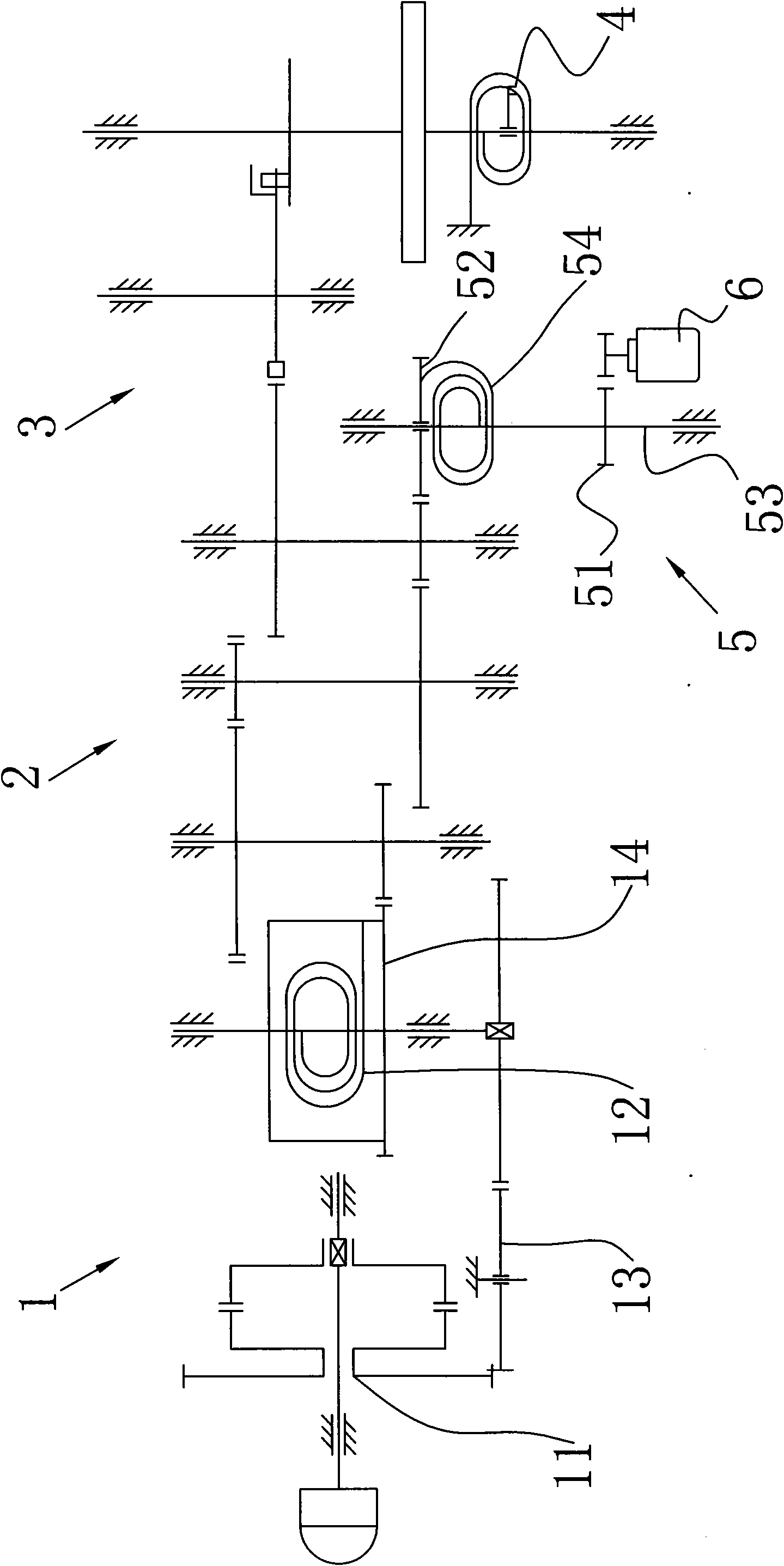
[0011] From figure 1 It can be seen that the present invention includes a kinetic energy collection and storage mechanism 1 , a transmission mechanism 2 , an escapement mechanism 3 , a speed regulating mechanism 4 , an incoherent kinetic energy collection and conversion mechanism 5 , and a generator 6 . The kinetic energy collection and storage mechanism 1, the transmission mechanism 2, the escapement mechanism 3, and the speed regulating mechanism 4 are connected sequentially, the input end of the incoherent kinetic energy collection and conversion mechanism 5 is connected with the transmission mechanism 2, and the output end of the incoherent kinetic energy collection and conversion mechanism 5 is connected to the generator 6, the non-coherent collection and conversion mechanism 5 includes a shaft 53, a sub-gear 51 fixed on the shaft 53, a rotatable female gear 52, and a hairspring 54. One end of the hairspring 54 is connected to the shaft 53, and the other end is connected t...

specific Embodiment 2

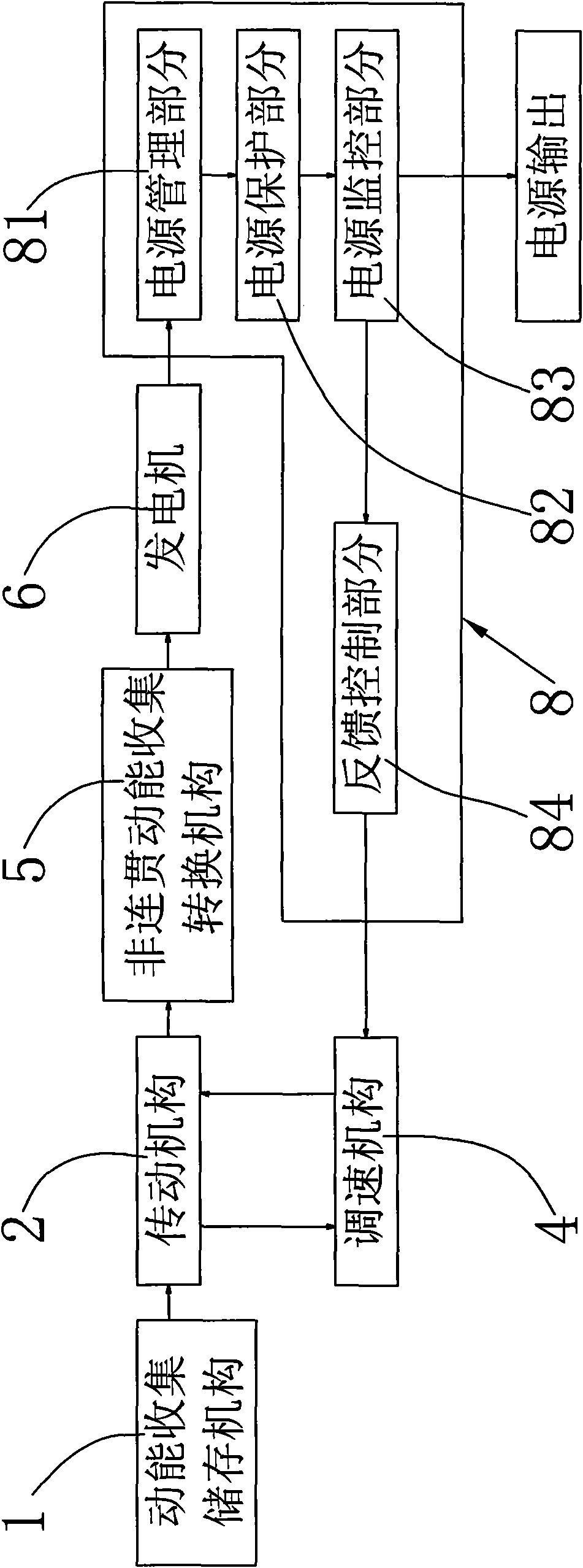
[0015] From image 3 It can be seen that the present invention can also connect a feedback control power supply system 8 at one end of the speed regulating mechanism 4 and the generator 6. This system mainly realizes the automatic adjustment of power. Through feedback control, the power consumption of the system can be adjusted in real time. , to achieve the effect of energy saving. The system includes a power management module 81, a power protection module 82, a power monitoring module 83 and a feedback control module 84 connected in sequence, the power management module 81 is connected with the generator 6, the feedback control module 84 is connected with the speed regulating mechanism 4, and the generator 6 The emitted power is output through the power monitoring module 83 . All the modules in the above-mentioned feedback control power supply system 8 can adopt modules in the prior art.

[0016] The main functions of the power management module 81 are rectification and vo...


PUM


Abstract

The invention discloses a power-collecting conversion power supply device, comprising a power-collecting storage mechanism, a transmission mechanism, an escapement mechanism, a generator, a speed-adjusting mechanism and a non-continuous power-collecting conversion mechanism. The speed-adjusting mechanism is connected with the escapement mechanism, the input end of the non-continuous power-collecting conversion mechanism is connected with the transmission mechanism, the output end of the non-continuous power-collecting conversion mechanism is connected with the generator, and the non-continuous power-collecting conversion mechanism turns non-continuous one-way rotation movement of the transmission mechanism into constant-speed rotation so as to drive the generator to generate electricity. With simple structure, the direct-current stable-voltage current output by the power-collecting conversion power supply device can be widely applied to national defense, scientific researches, universities and colleges, laboratories, industrial and mining enterprises, electrolysis, electroplating, direct-current motors, charging apparatus and the like.

Description

technical field [0001] The invention relates to a kinetic energy collection and conversion power supply device. Background technique [0002] With the rapid development of industrial and agricultural production and the improvement of people's living standards, the demand for electricity is increasing rapidly, and the contradiction between supply and demand is very prominent. At present, there are roughly several types of power generation: hydropower, thermal power, tidal power, atomic power and solar power. Although the existing hydraulic kinetic energy collection and conversion power supply device belongs to the utilization of renewable energy, the hydraulic resources available for power generation in a country are limited, and the construction of a complete set of devices requires high engineering costs. This kind of unit requires high production technology. , high cost, severe wear of the high-speed impeller during operation, and high maintenance costs, the actual operat...

Claims


Application Information

Patent Timeline
Patent Type & Authority Applications(China)
IPC IPC(8): H02K7/18H02P9/04
Inventor 罗波浪
Owner 罗波浪
Why Eureka
Try Eureka