
Detection system for detecting temperature alarm

A technology for detection systems and alarms, applied in alarms, thermometer testing/calibration, thermometers, etc., can solve the problems of lower detection accuracy, slow heating rate, and turbulent airflow, so as to improve detection accuracy, meet rapid heating, and heating rate fast effect

Active Publication Date: 2010-10-20
DONGGUAN CITY SIMPLEWELL TECH
View PDF1 Cites 4 Cited by
  • Summary
  • Abstract
  • Description
  • Claims
  • Application Information

AI Technical Summary

Problems solved by technology

[0002] The traditional detection system used to detect temperature-type alarms has simple structure, single function, slow heating rate, large temperature difference, and low detection accuracy. When some temperature-type alarms are tested, fast heating rate, small temperature difference, and The detection accuracy is high, so the traditional detection system used to detect temperature-type alarms cannot meet the needs of temperature-type alarms that require fast heating rates, small temperature differences, and high detection accuracy.
[0003] On January 28, 2009, the State Intellectual Property Bureau disclosed an invention patent for a detection system for detecting temperature-type alarms. Its patent number is 200820046081.9. The evaporator, heater, circulating fan, orifice plate, air grid, test station, test device installed on the test station, the test device and the lifting device installed on the top of the circulating air duct for the lifting of the test device The lifting mechanism is installed on the top of the circulating air duct and consists of a lifting cylinder and a chain connected to the cylinder shaft of the lifting cylinder. The test device is composed of a movable base and a guide set on the movable base. Rod and a hanging plate installed on the top of the guide rod, a test base is installed on the movable base, and the test base is connected to the driving motor installed at the bottom of the movable base in rotation. In the duct, since the guide rod is located in the circulating air duct, the air flow in the circulating air duct will be disturbed, which reduces the detection accuracy

Method used


Image

  • Detection system for detecting temperature alarm
  • Detection system for detecting temperature alarm
  • Detection system for detecting temperature alarm

Examples


Embodiment Construction

[0012] The best examples of the detection system for detecting temperature-type alarm described in the present invention below do not limit the protection scope of the present invention.

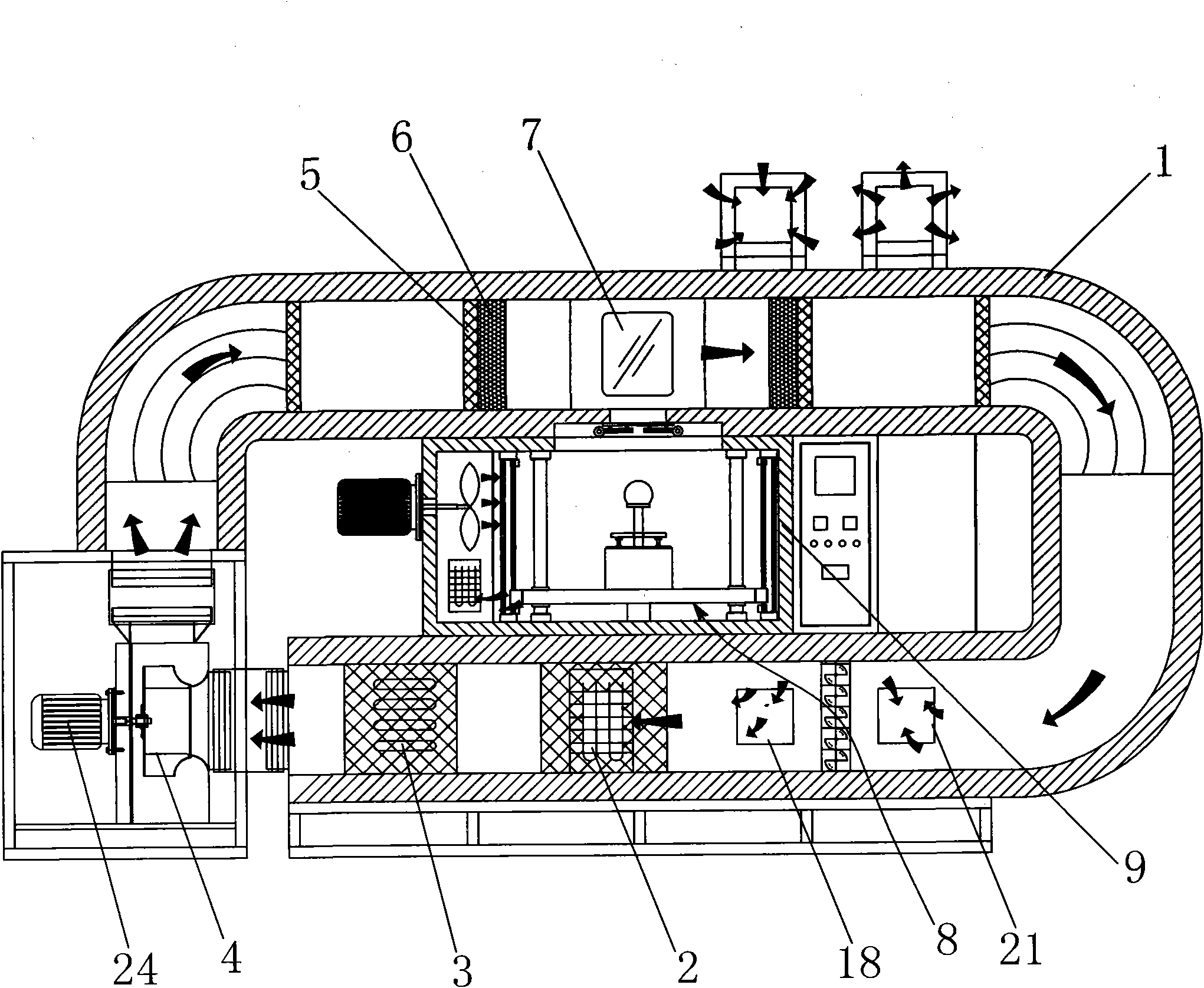
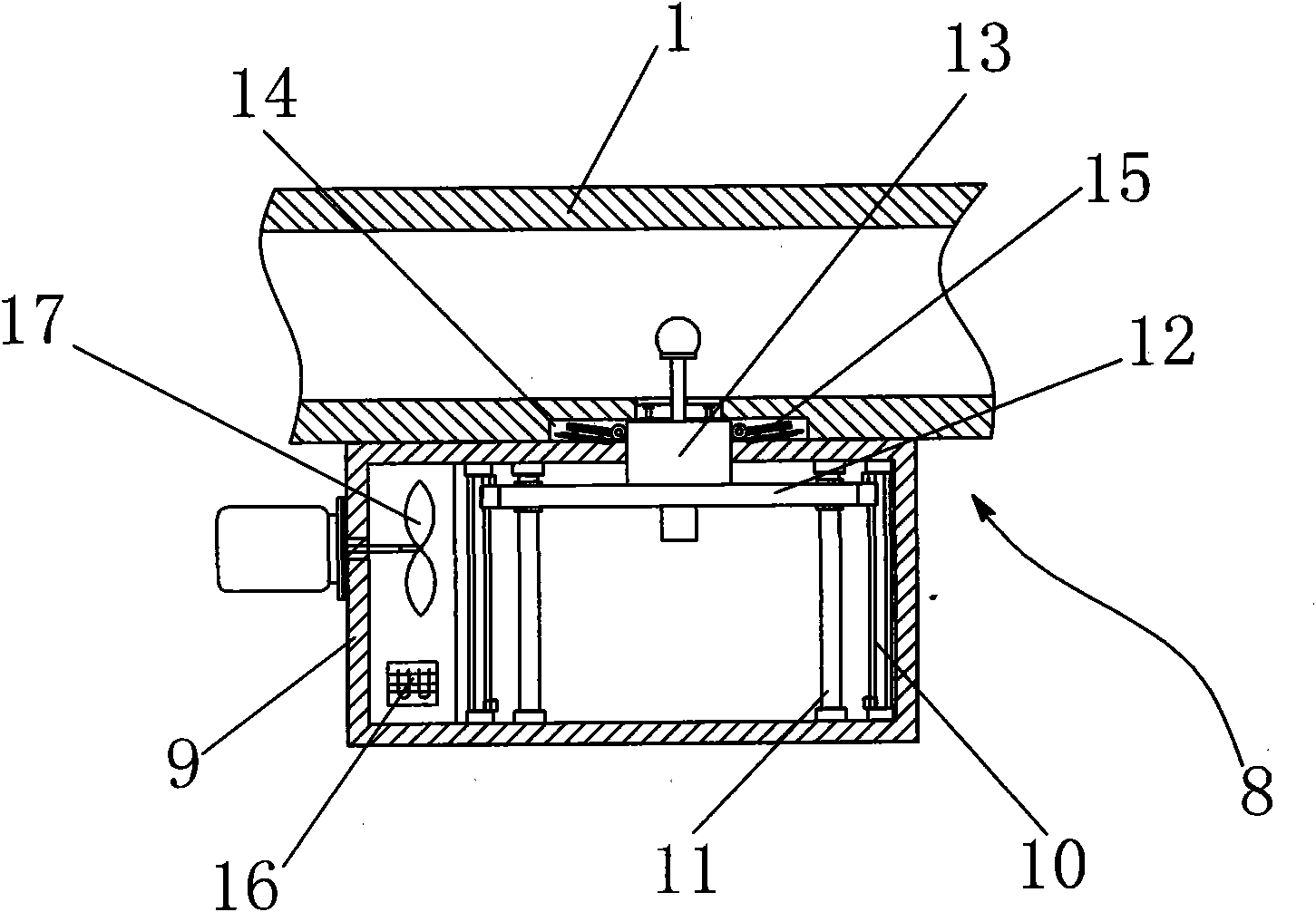
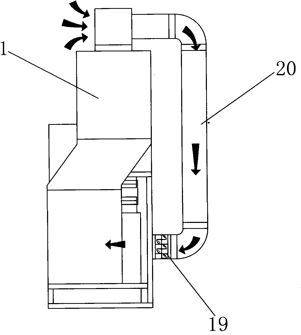
[0013] refer to figure 1 , figure 2 , image 3 , Figure 4 , providing a detection system for detecting temperature-type alarms, including a circulating air duct 1, and also includes a first evaporator 2, a heater 3, a first circulating fan 4, orifice plates installed in the circulating air duct 1 in sequence 5, air grid 6, test station 7, test device 8 installed on the test station 7, the test device 8 is a thermostat box 9 installed in the annular space of the circulating air duct 1, installed in the The drive cylinder 10 and the guide column 11 in the thermostat box 9 are set on the guide column 11 and the tray 12 connected to the drive cylinder 10, and the test piece bracket 13 installed on the tray 12 is formed. The circulating air duct 1 is provided with The opening 14 adapted to ...


PUM


Abstract

The invention discloses a detection system for detecting a temperature alarm. The system comprises a circulating air passage, a first evaporator, a heater, a first circulating fan, a pore plate, an air grid, a test working position and a test device, wherein the first evaporator, the heater, the first circulating fan, the pore plate, the air grid and the test working position are arranged in the circulating air passage in turn; the test device is arranged at the test working position and consists of a thermostat arranged in the annular space of the circulating air passage, a driving cylinder and a guide post arranged in the thermostat, a pallet which is sleeved on the guide post and in transmission connection with the driving cylinder and a test piece bracket arranged on the pallet; the circulating air passage is provided with an opening adapted to the test piece bracket; and when the driving cylinder drives the pellet to move upwards, the test piece bracket can make a test piece extend into the circulating air passage from the thermostat. The test piece is ascended and descended through the driving cylinder arranged in the thermostat without the assistance of a guide rod arranged in the circulating air passage so that turbulent flow in the circulating air passage can be effectively prevented. Therefore, the system has the advantages of high detection accuracy, high temperature rate, small temperature difference and high detection accuracy.

Description

technical field [0001] The invention relates to a detection device and a detection method using the detection device, more specifically, to a detection system for detecting temperature-type alarms. Background technique [0002] The traditional detection system used to detect temperature-type alarms has simple structure, single function, slow heating rate, large temperature difference, and low detection accuracy. When some temperature-type alarms are tested, fast heating rate, small temperature difference, and The detection accuracy is high, so the traditional detection system used to detect temperature-type alarms cannot meet the needs of temperature-type alarms that require fast heating rate, small temperature difference, and high detection accuracy. [0003] On January 28, 2009, the State Intellectual Property Bureau disclosed an invention patent for a detection system for detecting temperature-type alarms. Its patent number is 200820046081.9. The evaporator, heater, circ...

Claims


Application Information

Patent Timeline
IPC IPC(8): G08B29/00G01M19/00G01K15/00G01M99/00
Inventor 夏可瑜
Owner DONGGUAN CITY SIMPLEWELL TECH
Learn More